
Stability and Controls
Static Stability
When a mechanical system, such as an aircraft, is very slightly displaced from equilibrium, a non-equilibrium force system is generally created. If the sense of the resultant force or moment is such that it tends to restore the system to its original condition, then the system is said to be statically stable.
If, however, the sense of the resultant force or moment is such that it tends to cause the system to be displaced still further from its original condition, the system is statically unstable.
If the displacement causes no new force or moment to be created, so that the system has no tendency either to return to or to deviate further from its original condition, then the condition is a neutral one.
As a simple illustration, consider a marble resting at the topmost point of a smooth convex surface, or at the lowest point of a smooth concave surface, or on a smooth horizontal plane. These are three equilibrium conditions, illustrated in the three diagrams of Fig.
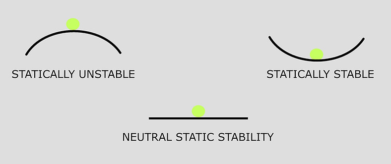
STATIC STABILITY
If, in the first case, the marble is slightly displaced, the normal reaction of the surface is no longer vertical, but has a sideways component which tends to push the marble further away from the central position. The condition is statically unstable.
In the second case, when the marble is slightly displaced, the normal reaction of the surface is again tilted, but its sideways component tends to restore the marble to the central position, so that this is a statically stable condition.
In the third case, when the marble is slightly displaced, the reaction of the surface remains vertical, and there is no resultant force on the marble, which therefore tends to remain in its new position. This condition is one of neutral static stability.
It is important to make the following points concerning the concept of static stability :
-
The concept only has real significance in the context of a system which is initially in equilibrium, although, it may be extended to apply to a steady manoeuvre, such as a steady, level turn.
-
It is concerned only with the tendency of the system to return to equilibrium, or otherwise, and not with what subsequently does happen to the system.
-
It is concerned only with the tendency created by infinitesimal displacement from equilibrium, and not with the consequences of relatively large displacements.
Longitudinal Stability
Longitudinal Stability is in the pitching plane and about the lateral axis. To be longitudinally stable, an aircraft must have a natural or inbuilt tendency to return to the same attitude in pitch after any disturbance. If the angle of attack is suddenly increased by a disturbance, then forces will be produced that will lower the nose and decrease the angle of attack.
The longitudinally stable aeroplane tends to maintain the trimmed condition of flight and is therefore easy for a Pilot to fly in pitch.
Lateral Stability
Lateral stability is the natural or inbuilt ability of the aeroplane to recover from a disturbance in the lateral plane, i.e. rolling about the longitudinal axis without any Pilot input. A disturbance in roll will cause one wing to drop and the other to rise.
When the aircraft is banked, the lift vector is inclined and produces a sideslip into the turn. As well as the forward motion through the air the aeroplane slips sideways due to the Lift and Weight not being directly opposed, causing a resultant sideways force on the aeroplane.
As a result of this sideslip, the aeroplane is subjected to a sideways component of relative airflow and forces are
generated that produce a rolling moment to restore the aeroplane to its original wings-level position.
The main contributor to Lateral Stability is the Wing.
Directional Stability
Directional stability of an aeroplane is its natural or inbuilt ability to recover from a disturbance in the yawing plane, i.e. about the normal axis. It refers to an aeroplane’s ability to ‘weathercock’ its nose into any crosswind, (i.e. a wind with a component from the side).
If the aircraft is disturbed from its straight path by the nose or tail being pushed to one side (i.e. yawed) then, due to its inertia, the aircraft will initially keep moving in the original direction. The aircraft will now be moving somewhat sideways through the air, with its side or keel-surfaces exposed to the airflow.
The vertical fin (or tail or vertical stabilizer) is simply a symmetrical aerofoil. As it is now experiencing an angle of attack, it will generate a sideways Lift force which tends to take the fin back to its original position. This restores the nose to its original position.
The powerful moment (turning effect) of the vertical fin, due to its large area and the length of the moment arm
between it and the Centre of Gravity, restores the nose to its original position. The greater the fin area and keel
surface area behind the CG, and the greater the moment arm, the greater the directional stability of the aeroplane.
Thus a forward CG is preferable to an aft CG as it gives a longer moment arm for the fin or vertical stabilizer.
A secondary effect of power or thrust is that caused by the slipstream. Propeller slipstream can affect the airflow over the fin, and therefore the fin’s effectiveness as a directional stabiliser. Changes in power cause changes in the slipstream and can lead to large changes in directional trim requirements.
Factors Affecting Longitudinal Stability
The longitudinal stability can be considered independently of the other two. In order to obtain stability in pitching, we must ensure that if the angle of attack is temporarily increased, forces will act in such a way as to depress the nose and thus decrease the angle of attack once again.
An ordinary upswept wing with a cambered aerofoil section cannot be balanced or ‘trimmed’ to give positive lift and at the same time be stable in the sense that a positive increase in incidence produces a nose-down pitching moment about the centre of gravity.
The position as regards the wing itself can be improved to some extent by sweepback, by wash-out (i.e. by decreasing the angle of incidence) towards the wing tips, by change in wing section towards the tips (very common in modern types of aircraft), and by a reflex curvature towards the trailing edge of the wing section.
But it is not only the wing that affects the longitudinal stability of the aircraft as a whole, and in general it can be said that this is dependent on four factors:
-
The position of the centre of gravity, which must not be too far back; this is probably the most important consideration.
-
The pitching moment on the main planes; usually tends towards instability, though it can be modified.
-
The pitching moment on the fuselage or body of the aeroplane; this too is apt to tend towards instability.
-
The tail plane -- its area, the angle at which it is set, its aspect ratio, and its distance from the centre of gravity. This is nearly always a stabilising influence.
Position of C.G. and C.P.
The further forward the CG of the aircraft the greater the moment arm for the tailplane, and therefore the greater the turning effect of the tailplane lift force. This has a very stabilising effect longitudinally. The position of the CG can be marginally controlled by the Pilot by the disposition of payload and fuel, usually done prior to flight. A forward CG leads to increased longitudinal stability and an aft movement of the CG leads to reduced longitudinal stability.
Limits are laid down for the range within which the CG must lie for safe flight and a prudent Pilot always loads his aeroplane and checks the trim sheet to ensure that this is so. If the CG is behind the legally allowable aft limit, the restoring moment of the tailplane in pitch may be insufficient for longitudinal stability. A CG further forward leads to more stability.
The more stable the aeroplane, the greater the control force the Pilot must exert to control or move the aeroplane in manoeuvres, which can become tiring. Also, if the CG is too far forward, the elevator may not be sufficiently effective at low speeds to flare the nose-heavy aeroplane for landing.
The pitching moment on the main planes; usually tends towards instability. The pitching moment on the fuselage or body of the aeroplane; this to is apt to tend towards instability.
Area and Location of tail plane
Let us consider a situation that is constantly occurring in flight. If a disturbance, such as a gust, changes the attitude of the aircraft by pitching it nose-up, the aircraft, due to its inertia, will continue initially on its original flight path and therefore present itself to the relative airflow at an increased angle of attack.
Changes in Tailplane Lift lead to Longitudinal Stability
With the same initial pitch-up caused by the disturbance and the aeroplane at first continuing in the original direction due to its inertia, the tailplane will be presented to the relative airflow at a greater angle of attack. This will cause the tailplane to produce a greater upwards Lift force (or decreased downwards force) than before the disturbance.
The increased tail-up lift of course gives a nose-down pitching moment, tending to return the aeroplane to its original trimmed condition.
Because of the great length of the moment arm between the centre of gravity and the tailplane, the Lift force produced by the tailplane need not be large for its turning effect to be quite powerful. As the tail is raised and the nose pitches back down, the original angle of attack is restored, the extra upwards lift force from the tailplane disappears and things are back to where they were prior to the disturbance. In this way the changes caused in the tailplane Lift force have led to longitudinal stability.
A good example of the stabilising effect of a tailplane is the passage of a dart or an arrow through the air, in which the tail-fins act as a tailplane to maintain longitudinal stability.
Sweep back
The effect of wing sweepback on rolling moment due to sideslip arises in much the same way as its effect on yawing moment due to sideslip. The aerodynamic force on a wing is largely determined by the wind velocity component normal to its leading edge. This component is greater on the forward wing, in the case of a swept wing in a condition of sideslip. The aircraft depicted is sideslipping to the right, and the normal component of velocity is greater on the starboard wing than on the port wing, so the starboard wing carries more lift. As a result, there is a rolling moment to port, which is stabilizing. Again, sweep-forward would have a destabilizing effect.
Longitudinal Dihedral
The tail plane is usually set at an angle less than that of the main planes, the angle between the chord of the tail plane and the chord of the main planes being known as the “longitudinal dihedral”. This longitudinal dihedral is a practical characteristic of most types of aeroplane, but so many considerations enter into the problem that it cannot be said that an aeroplane which does not possess this feature is necessarily unstable longitudinally.
In any case, it is the actual angle at which the tail plane strikes the airflow, which matters; therefore we must not forget the downwash from the main planes. This downwash, if the tail plane is in the stream, will cause the actual angle of attack to be less than the angle at which the tail plane is set. For this reason, even if the tail plane is set at the same angle as the main planes, there will in effect be a longitudinal dihedral angle, and this may help the aeroplane to be longitudinally stable.
Suppose an aeroplane to be flying so that the angle of attack of the main planes is 4 deg and the angle of attack of the tail plane is 2 deg; a sudden gust causes the nose to rise, inclining the longitudinal axis of the aeroplane by 1 deg
What will happen?
The momentum of the aeroplane will cause it temporarily to continue moving practically in its original direction and at its previous speed. Therefore the angle of attack of the main planes will become nearly 5 deg and of the tail plane nearly 3 deg. The pitching moment (about the centre of gravity) of the main planes will probably have a nose-up, i.e. unstable tendency, but that of the tail plane, with its long leverage about the centre of gravity, will definitely have a nose-down tendency. If the restoring moment caused by the tail plane is greater than the upsetting moment caused by the main planes, and possibly the fuselage, then the aircraft will be stable.
This puts the whole thing in a nutshell, but unfortunately it is not quite so easy to analyse the practical
characteristics which will bring about such a state of affairs; however the forward position of the centre of gravity and the area and leverage of the tail plane will probably have the greatest influence.
It is interesting to note that a tail plane plays much the same part, though more effectively, in providing longitudinal stability, as does reflex curvature on a wing, or sweepback with wash-out of incidence towards the tips.
When the tail plane is in front of the main planes there will probably still be a longitudinal dihedral, which means that this front surface must have greater angle than the main planes. The latter will naturally still be at an efficient angle, such as 4 deg, so that the front surface may be at, say, 6 deg or 8 deg. Thus it is working at a very inefficient angle and will stall some few degrees sooner than the main planes. This fact is claimed by the enthusiasts for this type of design as its main advantage, since the stalling of the front surface will prevent the nose being raised any farther, and therefore the main planes will never reach the stalling angle.
In the tailless type, in which there is no separate surface either in front or behind, the wings must be heavily swept back, and there is a ‘wash-out’ or decrease in the angle of incidence as the wing tip is approached, so that these wing tips do, in effect, act in exactly the same way as the ordinary tail plane.
Factor Affecting Lateral Stability
Lateral and directional stability will first be considered separately; then we shall try to see how they affect each other. To secure lateral stability we must so arrange things that when a slight roll takes place the forces acting on the aeroplane tend to restore it to an even keel.
In all aeroplanes, when flying at a small angle of attack, there is a resistance to roll because the angle of attack, and so the lift, will increase on the down-going wing, and decrease on the up-going wing. But this righting effect will only last while the aeroplane is actually rolling. It must also be emphasised that this only happens while the angle of attack is small; if the angle of attack is near the stalling angle, then the increased angle on the falling wing may cause a decrease in lift, and the decreased angle on the other side an increase; thus the new forces will tend to roll the aeroplane still further, this being the cause of auto-rotation.
Dihedral
The most common method of obtaining lateral stability is by the use of a dihedral angle on the main planes. Dihedral angle is taken as being the angle between each plane and the horizontal, not the total angle between the two planes, which is really the geometrical meaning of dihedral angle. If the planes are inclined upwards towards the wing tips, the dihedral is positive; if downwards, it is negative and called anhedral; the latter arrangement is used in practice for reasons of dynamic stability.
The effect of the dihedral angle in securing lateral stability is sometimes dismissed by saying that if one wing tip drops the horizontal equivalent on that wing is increased and therefore the lift is increased, whereas the horizontal equivalent and the lift of the wing which rises is decreased, therefore obviously the forces will tend to right the aeroplane.
High Wing
If the wings are placed in a high position and the centre of gravity is correspondingly low, the lateral stability
can be enhanced. When an aircraft sideslips, the lift on the lower wing becomes greater than that on the
higher one. Furthermore, a small sideways drag force is introduced. In consequence, the resultant force does not now pass through the centre of gravity so there will be a small moment which will tend to roll the aircraft back to a
level condition. This will occur even on a low-wing aircraft, but is more effective with a high wing because
the moment arm is greater. For this reason a high-wing aircraft requires less dihedral than a low-wing type.
Sweep Back
The effect of wing sweepback on lateral static stability may be considerable, and it is mainly because of the large positive contribution associated with this feature that highly swept wings on high performance aircraft may be mounted with anhedral, as observed above, to ensure that the aircraft is not too stable in this mode.
Factors Affecting Directional Stability
Consider first directional effects, and, in particular the static stability of an aircraft in the directional mode. When an aircraft is yawed, a side force is set up as a result of the asymmetry in attitude. This side force will, in general, give rise to a yawing moment. If the overall yawing moment, which results from a small, involuntary displacement in yaw, then the aircraft is statically stable in yaw.
Several components of the aeroplane contribute substantially to the directional static stability, in a positive or negative way.
Vertical Stabilizer
Just as a horizontal tailplane gives longitudinal static stability to an aircraft, so a vertical tail fin provides directional static stability, and it is the component of the aircraft which provides the principal stabilizing effect in this mode.
If a vertical tail fin on an aircraft which is sideslipping to the left, i.e., yawed to the right. The fin is at incidence, and experiences a side force to the right. This creates a yawing moment to port, which is a stabilizing moment. The side force on the tail fin may still be relatively small compared with that on the fuselage, which is destabilizing, but because its line of action is far aft of the aircraft centre of gravity, the yawing moment it creates is relatively large, and gives overall stability to the fuselage-fin combination.
Thus the principle behind the effect of the tail fin as a stabilizer is just the same as in the case of a dorsal or ventral fin. However, because it is much larger, and, in particular, has a much higher aspect ratio, it is effective at low angles of yaw. It remains effective until the angle of yaw is such that the fin incidence approaches its stalling value, but above this value the side force on the fin decreases with increasing angle of yaw, and the fin ceases to be effective as a stabilizer. It is at this point that the dorsal or ventral fin becomes important.
Because it stalls at a very much higher incidence, it takes over the stabilizing role of the tail fin at large angles of yaw. The fuselage by itself is seen to be basically unstable. The tail fin by itself is stable, and forms a stable combination with the fuselage, until it stalls. The addition of a dorsal fin stabilizes the fuselage fin combination at higher incidences. In practice, the tail fin is often so designed that it constitutes a combination of high aspect ratio fin with low aspect ratio fin.
Sweep Back
The tilting of the lift vector on each wing, associated with wing dihedral, is responsible for a minor destabilizing contribution to the yawing moment due to yaw. However, this contribution is insignificant compared with the effect of wing sweepback.
Sweep forward has a destabilizing effect where as a straight wing without dihedral has no significant effect on directional static stability.
Vertical Fin
To overcome this instability in the fuselage, it is possible to incorporate into its design dorsal or ventral fins. A dorsal fin is a small aerofoil, of very low aspect ratio, mounted on top of the fuselage near the rear. A ventral fin is similar, but mounted below. The effect of the fins, when the aircraft is yawed to starboard, say, is to create a side force to the right. The line of action of this force is well aft of the centre of gravity of the aircraft, so the yawing moment which results is to port, and this is a stabilizing effect.
However, at small angles of yaw, the fins are at low incidence, and because they are small, and, in particular, their aspect ratio is very low, resulting in small lift curve slope, the side force they create at such small angles will be very small, and they will be ineffective. Thus a fuselage which is unstable in yaw, will, when fitted with a dorsal or ventral fin, remain unstable at low angles of yaw.
However, at relatively high angles of yaw, the fins become more effective; because of their low aspect ratio they do not tend to stall, and this increase in effectiveness continues, so that the combination of fuselage with dorsal or ventral fin is stable at large angles of yaw.
We may note here that, while dorsal and ventral fins contribute in exactly the same way to directional static stability, a dorsal fin contributes positively to lateral static stability, while a ventral fin is de-stabilizing in this mode, for this reason, the dorsal fin is much the more common feature.
Spiral Divergence
If, on the other hand, an aircraft has too much directional stability, and too little lateral stability in proportion, a divergence of quite a different kind may ensue. A disturbance in yaw to starboard, say, would produce a stabilizing yawing moment which would quickly eliminate the motion in yaw. However, a rolling moment to starboard will also be created, causing the aircraft to roll to starboard, and consequently to lose height as a result of the tilting of the lift vector.
The aircraft will then enter a spiral dive which, if there is insufficient lateral stability, may get tighter and tighter. This kind of instability is known as spiral divergence.
Directional Divergence
The first of these is a form of instability known as directional divergence, and is a simple divergence in yaw which may occur if an aircraft is directionally statically unstable. Any disturbance in yaw then gives rise to a yawing moment in the same sense as the original displacement. Thus, if an aircraft flying straight and level experiences a small displacement in yaw to star-board, say, the result will be a yawing moment to starboard which will cause the displacement to increase.
Further, in the resulting yawed attitude, the aircraft will be subject to a side force to star-board, which will cause it to deviate from its original flight path. The side force will, at least up to a point, increase with angle of yaw, so that the flight path will continue to curve away from the original direction. If the aircraft is laterally statically stable, this directional divergence will occur without any significant degree of banking, and will continue until a limiting condition is reached in which the angle of yaw is so large that dN/dy is no longer positive.
In this condition, the aircraft would still be flying along a curved path at a very high angle of sideslip. This kind of divergence is not difficult to correct in flight, but it is avoided in design simply by building in sufficient positive directional static stability.
Dutch Roll
A third possible motion, which may ensue if the aircraft has positive directional static stability, but not so much, in relation to the lateral stability, as may lead to spiral divergence, is the lateral-directional oscillation, commonly known as the Dutch roll. Here a disturbance in yaw leads to an oscillation in yaw which, though damped, is only lightly so, and is therefore quite persistent. The displacement in yaw also gives rise to a rolling moment, and so initiates an oscillation in roll. If there is a high degree of lateral stability, such oscillations are quickly damped out. However, every period of the continuing oscillation in yaw acts in such a manner as to force further displacement in roll, and the resulting motion is a combination of oscillations in roll and yaw which have the same frequency, though they are out of phase.
This is the Dutch roll. It is usually only lightly damped, and may even be unstable.
In practice, design is a matter of compromise. The aircraft is first designed to have enough lateral stability so as not to be likely to suffer from spiral divergence. Enough directional stability is then built in to ensure that, in the first place, there will be no tendency towards directional divergence, and, in the second place, the relationship between the directional and static stability is such that the Dutch roll is adequately damped. As a result of this chosen ratio there may now be some renewed tendency towards spiral divergence, but this will tend to occur slowly and it is certainly preferable to an unstable Dutch roll.
The precise nature of any of these motions is determined by the various aerodynamic derivatives of a particular aircraft, and the relationships between them. The Dutch roll is often initiated deliberately in flight tests, since the measured data concerning amplitude, frequency and phase of the oscillations make it possible to estimate the values of several of these derivatives.
Aerodynamic Balancing
The forces which are necessary to move the various controls, i.e., the elevator, ailerons or rudder, may in some cases be very large, especially in the case of large aircraft, with large control surface, and/or at high speeds. This implies that the control surface hinge moments are too large to be acceptable from the pilot’s point of view. By careful design it is possible to make use of aerodynamic forces to help to deflect the control surface thus reducing the restoring hinge moment and the corresponding stick force. An aerodynamic device which performs this function is known as an aerodynamic balance.
There is several different types of aerodynamic balance, of which the most common are listed and described in the following paragraphs.
Set back the hinge
Downward deflection of an elevator, will normally produce a lift force, acting on the elevator through its centre of pressure. If the elevator hinges is at point, lift force produces a nose-down hinge moment, which is the restoring moment which the pilot has to counterbalance in order to keep the elevator down. If the hinge is set further back at, then for the same elevator deflection and elevator lift increment, the hinge moment will be much less. Thus aerodynamic balance is provided by the simple process of setting back the hinge.
It would appear that the hinge could be set as near to as one would wish to CP, and so provide any required amount of aerodynamic balancing. However, CP is not necessarily a fixed point, and in general moves forward with increasing elevator deflection. If the hinge is set too far back, there is a danger that under some conditions CP might be forward of the hinge, so that the resulting hinge moment would be nose-up. This would represent an unstable condition, in which the hinge moment coefficient is positive. Such a condition known as overbalance, and must be avoided. There is thus a limit to the amount of balance one can achieve by setting back the hinge, and there are also structural reasons why the hinge should not be set too far back.
Sealed nose balance
With this type of balance, a plate projects forward from the nose of the control surface. This plate, or tongue, is joined to the main part of the wing, tailplane or fin by a loose fold of impermeable fabric, which constitutes a seal between the regions above and below the control, or on the two sides of the control surface, in the case of a rudder.
The space above the tongue in the case of an elevator, say, is open to the air above to the tailplane and similarly the space below the tongue is open to the air below the tail. When the elevator is deflected downwards lift is increased on the elevator. This is the result of generally reduced pressure on the upper surface, increased pressure on the lower surface. In particular, the pressure just above the tongue is low, and just below it is high, so that there is an upward force on the tongue which provides a nose-up hinge moment, which is the required balancing moment.
Geared tabs
In this case, the control surface is fitted with a tab in such a way that when the main control moves downwards, say, the tab is automatically deflected upwards. This tab deflection produces a downward force on the tab, and hence a nose-up control hinge moment, which helps to keep the control down. The tab is geared to the main control, so that its deflection is always proportional to the control deflection, in accordance with a particular gear ratio. Thus the balancing effect increases with control deflection, but there is little danger of overbalancing.
Another related device is the so-called servo-tab, which is designed to provide all the hinge moment required to deflect the control. The principle is that when the pilot moves the control column this controls the tab directly. The deflected tab then creates a hinge moment which deflects the control. This is not strictly an aerodynamic balance, although the stick force necessary to deflect the tab is much less than that which would be required to deflect the main control directly, so that the effect is the same.
There are also various kinds of spring tabs which, in effect, distribute the stick force between the tab and the main control in varying ratios. Thus, the servo-tab is at one extreme and the geared balance tab is at the other. The ratio in which the load is distributed between tab and main control is simply determined by the mechanical linkages in the control circuit. The correct design of these linkages yields the required value for the hinge moment coefficient, i.e., the correct amount of aerodynamic balancing.
Frise aileron
The Frise type of balance consists in designing the shape of the control surface in such a manner that when it is deflected upwards the nose projects below the level of the main surface of the wing, say. The consequence, is a pressure on the nose which provides a nose-down hinge moment, and so reduces the restoring nose-up moment. .
The danger with this type of balance is that if large control deflections are used over balance is almost certain to result. For this reason, it is only used on ailerons, where two geared controls, the port aileron and the starboard aileron, move in opposite directions. The design is such that when the control moves downwards the nose does not project above the main wing surface, so that the down going aileron is not balanced at all. Thus, even if the upgoing aileron is overbalanced for large deflections, the combination of the two ailerons will generally remain stable. As we have seen, the extra drag on the side where the lift is reduced by upward aileron deflection also performs a useful function in offsetting adverse aileron yaw.
Horn balance
A horn balance consists simply in part of the control surface projecting far forward of the hinge line, so that it can be regarded as effectively as a heavily set-back hinge over part of the span of the control surface. When an elevator, say, is deflected downwards, there is a lift force on the horn which, being forward of the hinge line, provides a nose-up hinge moment to partly offset the nose-down moment on the rest of the elevator. The horn may be shielded or unshielded.
Aeroelastic Effects
We have hitherto made the assumption that the aircraft structure is perfectly rigid, i.e., that it cannot be deformed, no matter what loads are applied to it. This is, of course, an idealization which is not realized in practice. In fact, the airframe is subjected to aerodynamic loads which depend on its external shape. The consequence of these loads is to strain the airframe, so that its shape is slightly modified in some respects, and this change in shape leads to a modification of the aerodynamic loads. This interaction between the aerodynamic loads and the elastic strain of the airframe is known as aeroelasticity.
At relatively low speeds, the aerodynamic forces are relatively small, and the resulting, strain of the airframe produces only negligible effects. At higher speeds, the aerodynamic loads and the consequent strain are correspondingly greater and aeroelastic effects may be important, though it must be emphasized that they do not necessarily become important at the same speeds as those at which compressibility effects first arise.
The three important phenomena which could arise as a result of aeroelastic effects are:
Wing Torsional Divergence
Consider a wing at incidence. The pressure distribution, with the main loads located near the nose, is such as to cause the wing to twist in the nose-up sense. Because the structure is not perfectly rigid, it does in fact twist, and its shape becomes distorted relative to the wing root section. It twists about an axis known as the torsional axis of the wing, which is usually aft of the line of aerodynamic centres. This twist, by increasing the effective incidence, creates a lift increment which then acts forward of the torsional axis, so that the effect is unstable, in the sense that the more it twists the bigger is the twisting moment tending to cause it to twist still further. However, the tendency to twist is, of course, resisted by elastic forces due to the stiffness of the structure. This resistance to twist increases rapidly with the amount of twist, or strain, until it balances the aerodynamic twisting couple and equilibrium, is reached.
However, as the speed increases, the aerodynamic forces increase rapidly, in proportion to V, and therefore so also does the twisting moment. The elastic stiffness is not affected by speed, and so the amount of twist increases with speed. Eventually, a speed is reached at which the elastic resistance to twist is only just sufficient to counteract the twisting moment, and equilibrium is only achieved with the wing at breaking point. This speed is a critical speed called the wing torsional divergence speed, and any increase in speed above this value will result in structural failure-the wing will break off.
There is no real remedy for this situation. It is therefore essential to be able to predict this critical divergence speed, and to make the airframe strong and stiff enough to ensure that it is higher, by a substantial safety margin, than any speed which will ever be achieved in any condition in flight.
Similar considerations apply to wing bending, and there is a critical wing flexural divergence speed which, similarly, must be made so high that it will not be reached in flight.
Control Surface Flutter
Consider now an elevator which is hinged along a line which is well forward of the centre of gravity of the elevator, suppose the aircraft is in a steady condition when a sudden disturbance causes the tail, and with it the elevator, to be displaced upwards. Because of its inertia, the elevator will tend to rotate about its hinge line in such a way that downward deflection results. This will produce more lift on the tail, and thus the fuselage, which is an elastic structure, will bend, the tail moving further upwards. This will cause the elevator to deflect still further downwards, and so the process continues.
Resistance to this motion is, of course, provided by the elastic stiffness of the control circuit, which, if the stick is fixed, opposes the motion of the elevator. Similarly, the stiffness of the fuselage provides resistance to the tendency to bend. However, an oscillation may develop which, in certain circumstances is undamped, depending on the interaction of the inertia, aerodynamic and elastic effects described above. This oscillation is known as elevator flutter, and, if not checked, will ultimately cause structural failure.
There is generally a simple remedy. Suppose that the distribution of the mass of the elevator could be altered, so that its centre of gravity lies on the hinge line. Then the initial disturbance of the hinge line will not create any elevator deflection, and flutter will not occur. Further, if the centre of gravity of the elevator is forward of the hinge line, then upward movement of the hinge will cause the elevator to be deflected upwards, creating a downward increment in tail lift which, so far from creating the kind of instability which gives rise to flutter, acts as a damping factor and helps to eliminate the effects of the disturbance.
The careful arrangement of the mass distribution of the elevator, in order to eliminate the inertia-aeroelastic coupling which produces flutter, is called mass-balancing. It is not to be confused with aerodynamic balancing, to which it is totally unrelated. In the case of the simple kind of flutter just described, the object can be achieved by simply attaching a tongue to the nose of the control, and placing a mass on the end of it. This has the desired effect of moving the elevator centre of gravity forward. To eliminate the possibility of flutter even after a much more general kind of disturbance, more complete mass-balancing, involving the moments and products of inertia about the relevant axes, may be necessary.
The aileron may be caused to flutter in just the same way as the elevator, with the bending wing playing the role
corresponding to that of the bending fuselage. An example of a more complicated motion which might occur would be a combination of wing torsional and flexural oscillations due to aileron inertia. Again, the remedy lies in mass balancing of the aileron.
Mass balancing
Control surfaces are often balanced in quite a different sense. A mass is fitted in front of the hinge. This is partly to provide a mechanical balancing of the mass of the control surface behind the hinge but may also be partly to help prevent an effect known as ‘flutter’ which is liable to occur at high speeds. This flutter is a vibration which is caused by the combined effects of the changes in pressure distribution over the surface as the angle of attack is altered, and the elastic forces set up by the distortion of the structure itself.
All structures are distorted when loads are applied. If the structure is elastic, as all good structures must be, it will tend to spring back as soon as the load is removed, or changes its point of application. In short, a distorted structure is like a spring that has been wound up and is ready to spring back. An aeroplane wing or fuselage can be distorted in two ways, by bending and by twisting, and each distortion can result in an independent vibration. Like all vibrations, this flutter is liable to become dangerous if the two effects add up.
The flutter may affect the control surfaces such as an aileron, or the main planes, or both. The whole problem is very complicated, but we do know of two features which help to prevent it - a rigid structure and mass balance of the control surfaces. When the old types of aerodynamic balance were used, e.g. the inset hinge or horn balance, the mass could be concealed inside the forward portion of the control surface and thus two birds were killed with one stone; but when the tap type of balance is used alone the mass must be placed on a special arm sticking out in front of the control surface. In general, however, the problems of flutter are best tackled by increasing the rigidity of the structure and control-system components.
Large aircraft and military types now invariably have powered controls and these are much less sensitive to problems of flutter as the actuating system is very rigid.
Perhaps it should be emphasised that the mass is not simply a weight for the purpose of balancing the control surface statically, e.g. to keep the aileron floating when the control mechanism is not connected; it may have this effect, but it also serves to alter the moments of inertia of the surface, and thus alter the period of vibration and the liability of flutter.
It may help to make this clear if we realise that mass balance is just as effective on a rudder, where the weight is not involved, as on an elevator or aileron.
Control reversal
Consider a wing fitted with an aileron. The aileron is designed to produce positive increments in wing lift when it is deflected downwards. But downward deflection modifies the pressure distribution over wing and aileron in such a way that this increment in lift act well aft of the wing torsional axis, so that as a result the wing is twisted in the nose-down sense. This causes a reduction in effective incidence, and so a reduction in lift. However, the elastic stiffness of the wing creates a resistance to the wing twist, so that in the equilibrium condition the reduction in lift due to twist is generally less than the increase due directly to aileron deflection. Thus downward aileron deflection gives increase in lift overall, as expected, although the aileron effectiveness is reduced as a result of the twisting of the wing.
However, with increase in speed, the twisting moment, which arises from the aerodynamic loads, increase rapidly, while the elastic resistance is not changed, so that the wing twist more and more, for the same aileron deflection. There is a critical speed at which the loss in lift due to twist at a given aileron deflection is only just equal to the increase in lift due to that deflection and the aileron is then totally ineffective.
Above this speed, aileron deflection downwards will actually results in reduced lift overall and deflection, of the ailerons will result in a roll in the opposite sense to that which results from the same deflection at lower speeds. This phenomenon is known as aileron reversal and the speed at which it occurs is called the aileron reversal speed. This control result which can also occur in relation to the elevator and rudder, must be avoided, so that it is a design requirement that control reversal speeds must be higher than any physical speed to be achieved in flight.
Adverse Yaw
Consider first the effect of aileron deflection on yawing moment. Suppose that the starboard aileron goes up, and the port aileron down, in order to initiate a turn to starboard. The result of the downward deflection on the port wing is to increase the profile drag of that wing, while, conversely, the profile drag is slightly reduced on the starboard side.
There is also more induced drag on the port side because the lift on that side is higher. The result is a yawing moment to port, i.e., in the sense opposite to that of the desired turn. This phenomenon is known as adverse aileron yaw, and would be measured in terms of the aerodynamic dericative Nx , which is clearly positive, from the above argument. It may be alleviated by the use of ailerons of special design, known as Frise ailerons.
When an aileron is deflected upwards, the nose projects below the main wing surface, spoiling the flow and increasing the drag. When it is deflected downwards, there is no such projection, and no drag increment. The increased drag on the side on which the aileron is deflected upwards tends to offset to some extent the adverse aileron yaw.
‘Frise’, or other specially shaped ailerons, this is a patented device, the idea being so to shape the aileron that when it is moved downwards the complete top surface of the main plane and the aileron will have a smooth, uninterrupted contour causing very little drag, but when it is moved upwards the aileron, which is of the balanced variety, will project below the bottom surface of the main plane and cause excessive drag. This method has the great advantage of being simple, and it undoubtedly serves to decrease the bad yawing effect of the ailerons, and therefore it is often used. Unfortunately, its effects are not drastic enough.
Differential ailerons, is a delightfully simple device suffering only from the same defect that, although it provides a step in the right direction, it does not go far enough to satisfy our needs. Instead of the two ailerons moving equally up and down, a simple mechanical arrangement of the controls causes the aileron which moves upwards to move through a larger angle than the aileron which moves downwards, the idea being to increase the drag and decrease the lift on the wing with the up-going aileron, while at the same time the down-going aileron, owing to its smaller movement, will not cause excessive drag.