
Power Distribution
Introduction
Power distribution system in an aircraft is very essential in order for the power available at the appropriate generating sources, to be made available at the inputs of the power-consuming equipment and systems, which depends on the type of aircraft and its electrical system, number of consumers and location of consumer components.
For example, in a small light aircraft, electrical power requirements may be limited to a few consumer services and components situated within a small area, and the power may be distributed via only a few yards of cable, some terminal blocks, circuit breakers or fuses.
In a large multi jet transport aircraft on the other hand, literally miles of cable are involved, together with multiple load distribution busbars, protection networks, junction boxes and control panels.
Bus Bar
Bus bars are low impedance solid copper bars which are used for collection and distribution the output from the generating sources, which can be drilled to permit supply and distribution cables to be attached to them.
Bus bars are usually situated in junction boxes or distribution panels located at central points within the aircraft, and they provide a convenient means for connecting power supplies to the various consumer circuits; in other words, they perform a ‘carry-all’ function.
Bus bars vary in form dependent on the methods to be adopted in meeting the electrical power requirements of a particular aircraft type.
In its simplest form a bus bar can take the form of a strip of interlinked terminals, while in the more complex systems main bus bars are thick metal (usually copper) strips or rods to which input and output supply connections can be made.
The strips or rods are insulated from the main structure and are normally provided with some form of protective covering. Flat, flexible strips of braided copper wire are also used in some aircraft and serve as subsidiary bus bars.
Busbar Systems
The reason for the use of bus bar system is as follows
-
That in the event of power source failures, Power-consuming equipment must not be deprived of power unless the total power demand exceeds the available supply.
-
Faults on the distribution system (e.g. fault currents, grounding or earthing at a bus bar) should have the minimum effect on system functioning and should constitute minimum possible fire risk.
-
Power-consuming equipment faults must not endanger the supply of power to other equipment.
These requirements are met in a combined manner by paralleling generators where appropriate, by providing adequate circuit protection devices, and by arranging for failed generators to be isolated from the distribution system.
The management of potential failures is addressed by categorizing the various loads and then disconnecting them in accordance with a predetermined sequence. Therefore all consumer services are categorise into their order of importance as follows
Vital Services
Vital services are those which would be required after an emergency wheels-up landing, e.g. emergency lighting and crash switch operation of fire extinguishers. These services are connected directly to the battery.
Essential Services
Essential services are those required to ensure safe flight in an in-flight emergency situation. They are connected to DC and AC bus bars, as appropriate, and in such a way that they can always be supplied from a generator or from batteries.
Non-essential Services
Non-essential services are those which can be isolated in an in-flight emergency for load shedding purposes (see below), and are connected to DC and AC bus bars, as appropriate, and are supplied from a generator.
The figure below indicates a DC distribution system as per the importance of required for the various equipments.

BASIC AIRCRAFT POWER DISTRIBUTION SYSTEM
The vital services are connected to the battery busbar which is also called as hotbus bar since it is directly connected to the aircraft battery.
The essential DC services are connected to the central busbar and the essential AC services are connected are connected via inverted no 1, which is connected to the central busbar. The central busbar is power by both the generators via their respective busbars in the event of failure of one generator the central busbar will still remain powered. The central bubar can also be power by external ground power, when the aircraft is on ground.
The non-essential DC services are powered by the respective generator busbar and the non-essential AC services are power by inverters, which are supplied by the respective generator bubars.
In the event of failure of any of the generators the non essential services the respective generator is disconnected and the other non essential services can or cannot be disconnected depending upon the load on the systems, this process is called as load shedding, and only the essential and vital services are powered.
In the event of both generator failure the vial services are still power by the battery for the safe flight of the aircraft for the rated duration of the battery.
Small/Single Engine Power Distribution System
A small or single engine power distribution system is very simple it generally (but not limited to) consist of a generator, to which is connected a voltage regulator, over voltage protection unit. The system also includes a generator cut out relay which prevents the supply from the busbar to the generator, preventing its motoring action. All theses systems together form the protection devices for the system.
It consists of one or two busbars to which the load or the electrical equipments are connected and a Battery which is connected to the bus bar so it can be charged under normal operation and in the event of emergency or power failure supply voltage to the busbar.
A failure light can also be included to indicate the failure of the generator.

TYPICAL SMALL/SINGLE ENGINE POWER DISTRIBUTION SYSTEM
Large Aircraft Systems
Larger (commuter, business and passenger) aircraft have many more electrical systems compared with general aviation aircraft; there is a requirement for a comprehensive approach to account for potential failures of generators, wiring, etc.
There are three main types of distribution system generally used:
-
Split bus System
-
Parallel System
-
Split Parallel System
Split Bus System
Split busbar system is generally used in twin generation system, and a completely isolated is achieved between both the generators. These type of systems are also called a non-parallel system used. The advantage of a split-bus system is that the generators do not need to be operating at exactly the same frequency and can be running out of phase with each other.
Primary power is based on two main AC integrated drive generators (typically 40 kVA on each engine). An APU generator (40 kVA) is used as back-up in the event of a main integrated drive generator (IDG) failure.
Secondary power is derived from step-down transformers to provide 26 V AC; transformer rectifier units (TRU) provide 28 V DC for the DC busbars and battery charging.
Each generator bus is connected to a transfer bus via transfer relays which are controlled by the bus transfer switch. The switch are generally retained in auto position by a guarded cover. In the event of a generator failure, the remaining generator (engine or APU) supplies essential loads.
Control of the system is via a number of flight compartment switches which are of momentary type and are returned to neutral position when released, control breakers like GCB (Generator Control Breaker) and BTB (Bus Tie Breakers) and relays arranged to connect and disconnect the generators and busbars. An interlocking circuits between the the switch and relay enable proper sequencing of breakers and overall system operations.
A source or power switched on or entering onto the system takes priority and will automatically disconnect any existing power source on the same bus.
It also consist of an external power receptacle, which is use to connect ground/external power when the aircraft is on ground. The external power connection to the busbar is controlled by external power contractor. The external power required is 115V, 3 phase, 400 Hz.

SPLIT BUSBAR SYSTEM / NON PARALLEL BUSBAR SYSTEM
When the external power is connected and switched on, the external power contactor closed and energizes both bus-tie breaker (BTB) to connect power to the whole system. The system is controlled by a single ground power switch.
The APU generator is connected to the entire system by its own breaker, however unlike the external ground power the APU generators are controlled by two switches one for controlled the bus-tie breaker 1 (BTB1) and other for bus-tie breaker 2 (BTB 2). Each switch is capable of operating independently.
When an engine is started and its generator is switched on its bus-tie breaker (BTB) opens and allows the closing of the its generator control breaker (GCB), which allows its busbar to be powered by the generator. However the other system is still power by the external power/ APU. Once the other engine is started and its generator switch is selected on its bus-tie breaker (BTB) opens and allows the closing of the its generator control breaker (GCB), which allows its busbar to be powered by the generator. Due to this the external power contractor trips open if it is powered by eternal ground power or the APU breaker trips if it was connect to the APU generator.
Under normal flight configurations, each engine generator supplied to its respective busbars via its own generator circuit breaker (GCB). With the help of interlock circuits the bur-tie breakers (BTB) kept open and hece it prevents the interconnection or paralleling of generators.
In the event of loss of power from one of the generators its generator control breaker (GCB) opens, thus isolating its busbar. However as the generator control breaker (GCB) opens, a DC signal via its auxiliary contacts flows from the other generator control unit to the alternate coil of transfer relay via bus transfer switch. Thus allowing power to be supplied for the other generator.
APU generator can be switched on and can power the faulty generator busbar, thus allowing normal operation of the system. However in case of the second generator failure the process of load shedding is started.
Parallel Bus System
The electrical distribution system on larger passenger aircraft (with three or four engines) the spil busbar system becomes too complex, hence they are based on a parallel load distribution system.
In this configuration, all generators are connected to their own AC load bus via their generator control breaker (GCB) and a distribution bus via their bus-tie breakers (BTB). This allows any generator to supply to load bus to provide equal load-sharing.
The distribution bus also called as synchronisation busbur, is split into two parks by the split system breaker (SSB) which, in the open position allow the generator to operate in two parallel pairs.
The APU and external power are connected to the distribution bus via its own contactors.
All generator voltages, frequencies and phase relationships must be controlled to very close tolerances. Any attempt to connect generators in parallel before these conditions are met could result in loss of generator power due to large circulating currents.

PARALLEL BUSBAR SYSTEM
Under normal inflight operations when all four GCBs and BTBs are closed; all four generators are synchronized and connected to the tie (or synchronized) distribution busbar.
If one generator fails, its GCB is opened and this isolates the generator from its own load busbar. That busbar is now powered from the remaining generators. If this bus becomes overloaded, its GCB and BTB are automatically opened and is it isolated from the rest of the system.
When more than two generator failures, load-shedding is introduced.
Split/Parallel Bus System
This is a flexible load distribution system for large passenger aircraft; it provides the advantages of the parallel system and maintains isolation when needed.
Primary power supply features include: one IDG per engine, two APU generators and two external power connections. A split system breaker links left and right sides of distribution system.
Any generator can supply any load busbar; any combination of generators can operate in parallel
Standby and Essential Power
On an multi engine aircraft, an essential 115 VAC power is provided as a single phase supply, to the system,in an event of emergency.

STANDBY AND ESSENTIAL POWER DISTRIBUTION SYSTEM
This is selected from one phase of a main busbar. (On a four-engined aircraft, the normal source is the main AC bus number four.) If this normal source fails, a supply is maintained by selecting a different main bus from the remaining systems.
The standby AC bus is normally powered from the essential AC bus; if this source fails, a static inverter (supplied from the main battery) is selected to provide standby AC power.
Some aircraft distinguish between battery busbars (that can be disconnected from the battery) and hot battery bus bars that are connected directly to the battery, i.e. without any switching.
This arrangement splits the battery bus with a direct connection (the ‘hot’ battery bus), and a switched battery bus controlled by the battery switch.
Essential DC power is from a transformer rectifier unit (TRU) powered from the essential AC bus. Standby AC and DC bus power is normally from the respective essential supplies; when selected ON, standby AC and DC power is from an inverter and the battery respectively.
External Power
Electrical power is required for the starting of engines, operation of certain services during "turn-round" servicing periods at airports, e.g. lighting, and for the testing of electrical systems during routine maintenance checks.
The batteries of an aircraft are, of course, a means of supplying the necessary power, and although capable of effecting engine starts their capacity does not permit wide scale use on the ground, they are restricted to the supply of power under emergency conditions.
It is necessary, therefore, to incorporate a separate circuit through which power from an external ground power unit, may be connected to the aircraft's distribution busbar system.
In its simplest form, an external power supply system consists of a connector located in the aircraft at a conveniently accessible point (at the side of a fuselage for example) and a switch for completing the circuit between the ground power unit and the busbar system

TYPICAL EXTERNAL POWER CONNECTION
Many aircrafts required different type of circuit depending on the type of supply AC or DC and the degree of complexity of the power distribution system
In basic DC power distribution system the ground or external power supply connection consists of two positive pins and one negative pin; one of the positive pins is shorter and of smaller diameter than the remaining pins.
The pins are enclosed by a protective shroud, and the complete unit is normally fitted in a recessed housing located at the appropriate part of the airframe structure.
The short positive pin is connected in the coil circuit of the external power relay. The reason for this is that in the event of the external supply socket being withdrawn with the circuit ''live'', the external power relay will de-energise before the main pins are disengaged from the socket.
This ensures that breaking of the supply takes place at the heavy-duty contacts of the relay thus preventing arcing at the main pins.

DC EXTERNAL POWER SYSTEM
The external power supply for modern AC system are different for the DC system since modern aircraft uses three phase supply.
It consists of six pins instead of the the three pic DC configuration, where out of the six pins three are the individual phases (A,B and C), the fourth pin is Neutral, and pin the remaining two pins are connected to the controlled circuits and are smaller in size and diameter.
The external power is connected to the receptacle, a three-phase supply is fed to the main contacts of the external power breaker and to a voltage and phase sequence protection unit. If the phase sequence is correct the protection unit completes a circuit to the control relay coil, thus energising it.
The circuit is controlled by an external power switch connected to a busbar supplied with 28 volts d.c. from the aircraft battery system. When the switch is set to the "close" position current flows across the main contacts of the energised control relay, to the ''close" coil of the external power breaker, thus energising it to connect the external supply to the three phase a.c. main busbar.
The external power supply is disconnected by selecting the "trip" position on the external power switch. This action connects a d.c. supply to the trip coil of the external power breaker, thus releasing its main and auxiliary contacts and isolating the external power from the a.c. main busbar.
A single-phase supply is also fed to an amber light which comes on to indicate that external power is coupled, and to a voltmeter and frequency meter via a selector switch.

THREE PHASE EXTERNAL POWER SYSTEM
Auxiliary Power Unit (APU)
Modern aircrafts are made independent of ground support equipment by the incorporation of an auxiliary power unit (A.P.U.) in the tail section which, after being started by the aircraft's battery system provides power for engine starting, ground air conditioning and other electrical services.
The APU is also used for supplying power in flight in the event of an engine driven generator failure and for supplementing the delivery of air to the cabin during take-off and climb.
An A.P.U. consists of a small gas turbine engine, a bleed air control and supply system, and an accessory gearbox.
The gas turbine comprises a two stage centrifugal compressor connected to a single stage turbine.
The bleed air control and supply system automatically regulates the amount of air bleed from the compressor for delivery to the cabin air conditioning system.
In addition to those accessories essential for engine operation, e.g. fuel pump control unit and oil pumps, the accessory gearbox drives a generator which is of the same type as those driven by the main engines, and having the same capacity.
A motor for starting the APU is also secured to the gearbox and is operated by the aircraft battery system or, when available, from a ground power unit. In some types of APU the functions of engine starting and power generation are combined in a starter/generator unit.
In order to record the hours run, an hour meter ls automatically driven by an APU
control and protection unit
.jpg)
BASIC APU BLOCK DIAGRAM
Ram Air Turbine (RAT)
In the event of generator failure, continuous power can be provided by a ram air turbine (RAT). Also referred to as an air-driven generator, this is an emergency source of power that can be called upon when normal power sources are not available.
The RAT is an air-driven device that is stowed in the wing or fuselage and deployed in the event that the aircraft loses normal power.
When deployed, it derives energy from the airflow, RATs typically comprises a two-bladed fan, or propeller that drives the generator shaft via a governor unit and gearbox; the gear ratios increase the generator shaft speed.
The RAT can be deployed between aircraft speeds of 120 to 430 knots; some RATs feature variable pitch blades operated by a hydraulic motor to maintain the device at typical speeds of 4,800r.p.m.
Typical RAT generators produces an AC output of 7.5kVA to a TRU. Heaters are installed in the RAT generator to prevent ice formation. RATs can weigh up to 400lbs on very large transport aircraft, with blade diameters of between 40 and 60 inches depending on power requirements.
.jpg)
RAM AIR TURBINE (RAT)
Electrical Power Control & Indication
The Control Panel for various types of aircraft differ with respect to the distribution systems used and also with respect to each manufacturer.
A control panel that features for a split bus system consist of the following controls and indications
-
Ground power available: It illuminates blue when external power supply is connected and available to use.
-
Ground power on/off switch: It is used to select ground power onto the aircraft
-
Transfer bus off: It illuminates amber when the transfer relay is de-energized (either normal or transfer)
-
Bus off: It illuminates amber when both respective generator circuit breakers (GCB) and bus tie breakers (BTB) open
-
Generator bus off: It illuminates blue if the respective GCB is open
-
APU generator bus off: It illuminates blue APU running at 95% RPM, no power from generator
-
Bus Transfer Switch: It is use to select the bus transfer relay. It is generally retained in "Auto" position by the help of a switch guard. Other Positions are "On" and "Off".

TYPICAL ELECTRICAL CONTROL PANEL
In olden aircrafts the indication of the voltage and current was provided on the same panel by the help of a voltmeter and ammeter. However in the modern aircraft a separated panel is provided for the indication along with other maintenance functions like fault detection and other non essential system control switches like IFE.

ELECTRICAL INDICATION PANEL
Another type of electrical panel found on modern aircraft consist of push button instead of toggle switches, the function of the switch remain same to select the respective engine generator, APU generator or external power, transfer switches or in some case IDG disconnect switches.

MODERN AIRCRAFT ELECTRICAL CONTROL PANEL
In the modern aircraft the indication of the electrical system is provided by on the display units in the form of schematic diagrams which indicate the connection between the various buses and also indicate its respective voltage and current values.

MODERN AIRCRAFT ELECTRICAL INDICATION SYSTEM
Electrical Wire Interconnection System (EWIS)
EWIS relates to any wire, wiring device, or combination of these, including termination devices, installed in the aircraft for transmitting electrical energy between two or more termination points.
Electrical wires and cables are constitute the framework of power distribution systems and forms an integral part of the aircraft requiring careful installation, since electrical and electronic systems are all interconnected with wires and cables. Wire and cable installations cannot be considered (or treated) as ‘fit and forget’ . Therefore direct inspection and maintenance requirements for safe and economic operation of an aircraft.
The differences between a wire and a cable relate principally to their constructional features.
A wire is a single solid rod or filament of drawn metal enclosed in a suitable insulating material and outer protective covering.
A cable is usually made up of a conductor composed of a group of single solid wires stranded together to provide greater flexibility, and enclosed by insulating material and outer protective covering. A cable may be either of the single core type, i.e., with cores stranded together as a single conductor, or of the multicore type having a number of single core cables in a common outer protective covering.
Factors Affecting Types of Wire Selection
The type of aircraft wiring depends not only upon current carrying capacity but also on the environment in the wire needs of be installed. The aircraft wiring is exposed to a variety of environmental and in-service conditions including contaminants, for example:
-
Hydraulic Fluid
-
Fuel and/or Oil
-
Temperature Extremes
-
Abrasion
-
Vibration
Types of wire and cable
Wires and cable types used in an aircraft can be categorized with their specific uses and applications:
-
Airframe wires and cables
-
Equipment wires and cables
-
Ignition system cables
-
Thermocouple cables
-
Data bus cables
-
Radio-frequency (RF) cables
Wires and cables are designed and manufactured for duties under specific environmental conditions and are selected on this basis. General-purpose wiring used in the airframe comprises the majority of the installed material. There are also special considerations for wiring, e.g. when routed through fire zones. The materials used for the conductor and insulation must take these factors into account.
The names adopted for the various types are derived from contractions of the names of the various insulating materials used. For example, ''NVVIN" is derived from "NYlon" and from polyVINyl-chloride (P.V.C.); and ''TERSIL" is derived from polyesTER and SILicone.
Cables may also be further classified by prefixes and suffixes relating to the number of cores and any additional protective covering. For example, "TRINYVIN" would denote a cable made up of single Nyvin cables, and if suffixed by "METSHEAT the name would further denote that the cable is enclosed in a metal braided sheath.

TYPES OF WIRE USED IN AIRCRAFT
Two types of metals are used for conductors, i.e. copper (which may also be tinned, nickel-plated or silver-plated depending on cable application) and aluminium.
Copper has a very low specific resistance and is adopted for all but cables of large cross sectional areas. An aluminium conductor having the same resistance as a copper conductor, has only two-third of its weight but twice the cross-sectional area of the copper conductor.
Wire size
Wire sizes used on aircraft are defined in accordance with the American Wire Gauge or Gage (AWG). For a given AWG, the wire will have a specified diameter and hence a known conductance (the reciprocal of resistance). Cable size relates to the conductor’s diameter; the overall wire or cable diameter is therefore larger due to the insulation.
The largest wire size is 0000 AWG; the smallest is 40 AWG. The range of AWG wire/cable sizes is detailed in the Appendices. Selection of wire size depends on the specified current to be conducted. Larger diameter wires add weight, but offer less voltage drop for a given length and lower heating effect due to I²R losses.
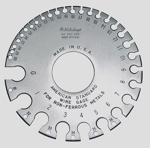
AWG MEASURING GAUGE
Wire Identification
Wire identification is printed on the outer surface of the sheath at intervals between 6 and 60 inches. This includes the wire part number and manufacturers commercial and government entity (CAGE) designation. The printing is either green or white (depending on the actual colour of the wire).
A colour code scheme is also adopted particularly as a means of tracing the individual cores of multicore cables to and from their respective terminal points. In such cases it is usual for the insulation of each core to be produced in a different colour and in accordance with the appropriate specification.
Another method of coding, and one used for cables in three phase circuits of some types of aircraft, is the weaving of a coloured trace into the outer covering of each core; thus red -(phase A); yellow - (phase B); blue - (phase C).

TYPICAL WIRE IDENTIFICATION METHOD
Routing of Wires and Cables
The quantity of wires and cables required for a distribution system depends on the size and complexity of the systems. However, regardless of quantity, it is important that wires and cables be routed through an aircraft in a manner which, is safe, avoids interference with the reception and transmission of signals by such equipment as radio and compass systems, and which also permits a systematic approach to their identification, installation and removal, and to circuit testing.
Various methods, dependent also on size and complexity, are adopted but in general, they may be grouped under three principal headings:
-
Open Loom,
-
Ducted Loom,
-
Conduit.
Open Loom: In this method, wires or cables to be routed to and from consumer equipment in the specific zones of the aircraft, are grouped parallel to each other in a bundle and bound together with waxed cording or p.v.c. strapping. A loom is supported at intervals throughout its run usually by means of clips secured at relevant parts of the aircraft structure.
The composition of a cable loom is dictated by such factors as
-
Overall Diameter
-
Temperature Conditions
-
Type of current, i.e. whether alternating, direct, heavy-duty or light-duty
-
Interference resulting from inductive or magnetic effects
-
Type of circuit with which cables are associated
Magnetic fields exist around cables carrying direct current and where these cables must interconnect equipment in the vicinity of a compass magnetic detector element, it is necessary for the fields to be cancelled out. This is achieved by routing the positive and earth-return cables together and connecting the earth return cable at an earthing point located at a specific safe distance from the magnetic detector element of a compass system.
Ducted Loom : This method is basically the same as that of the open loom except that the bundles are supported in ducts which are routed through the aircraft and secured to the aircraft structure. Ducts may be of aluminium alloy, resin impregnated asbestos or moulded fibre-glass. reinforced plastic.
In some applications of this method, a main duct containing several channels may be used, each channel supporting a cable loom corresponding to a specific consumer system, For identification purposes; each loom is bound, with appropriately coloured waxed cording.
Conduits : They are generally used for conveying cables in areas where there is the possibility of exposure to oil, hydraulic or other fluids. Depending on the particular application, conduits may take the form of either plastic, flexible metal or rigid metal sheaths. In cases where shielding against signal interference is necessary the appropriate cables are conveyed by metal conduits in contact with metal structural members to ensure good bonding.
Cable Seals : ln pressurized cabin aircraft it is essential for many cables to pass through pressure bulkheads without a "break" in them and without causing leakage of cabin air. This is accomplished by sealing the necessary apertures with either pressure bungs or pressure- proof plugs and sockets.
Special Purpose Cable
For certain types of electrical systems, cables are required to perform a more specialized function than that of the cables some of them are as follows
Ignition Cables
These cables arc used for the transmission of high tension voltages in both piston engine and turbine engine ignition systems, and are of the single-core stranded type suitably insulated, and screened by metal braided sheathing to prevent interference. The number of cables required for a system corresponds to that of the sparking plugs or igniter plugs as appropriate, and they arc generally made up into a complete ignition cable harness.
Depending on the type of engine installation, the cables may be enclosed in a metal conduit, which also forms part of a harness, or they may be routed openly. Cables are connected to the relevant system components special end fittings comprising either small springs or contact caps secured to the cable conductor, insulation and a threaded coupling assembly.
Thermocouple Cables
These cables arc used for the connection of cylinder head temperature indicator and turbine engine exhaust gas temperature indicators to their respective thermocouple sensing elements. The conducting materials are normally the same as those selected for the sensing element combinations, namely, iron and constantan or copper and constantan for cylinder head thermocouples, chromel (an alloy of chromium and nickel) and alumel (an alloy of aluminium and nickel) for exhaust gas thermocouples.
ln the.case of cylinder head temperature indicating systems only one thermocouple sensing element is used and the cables between it and a firewall connector arc normally asbestos covered.
For exhaust gas temperature measurement a number of thermocouples are required to be radially disposed in the gas stream, and it is the usual practice therefore, to arrange the cables in the form of a hamess tailored to suit a specific engine installation.
The insulating material of the harness cables is either silicone rubber or P.T.F.E. Impregnated fibreglass. The cables terminate at an engine or firewall junction box from which cables extend to the indicator.
The insulating material of extension cables is normally of the polyvinyl type, since they are subject to lower ambient temperatures than the engine harness. In some applications extension cables are encased in silicone paste within metal braided flexible conduit.
Co-axial Cables.
Co-axial cables contain two or more separate conductors, the innermost conductor may be of the solid or stranded copper wire type, and may be plain, tinned, silver-plated or even gold-plated in some applications, depending on the degree of conductivity required.
The remaining conductors are in the form of tubes, usually of fine wire braid, the insulation is usually of polyethylene or Teflon.
Outer coverings or jackets serve to weatherproof the cables and protect them from fluids, mechanical and electrical damage. The materials used for the coverings are manufactured to suit operations under varying environmental conditions.

CO-AXIAL CABLE
Co-axial cables have several main advantages.
First, they are shielded against electrostatic and magnetic fields; an electrostatic field does not extend beyond the outer conductor and the fields due to current flow in inner and outer conductors cancel each other.
Secondly since co-axial cables do not radiate, then likewise they will not pick up any energy, or be influenced by other strong fields.
The installations in which coaxial cables are most commonly employed are radio, for the connection of antennae, and capacitance type fuel quantity indicating systems for the interconnection of tank units and amplifiers.
Aircraft Wire Connections
In general, there are two connecting methods adopted and they can be broadly categorized by the frequency with which units must be connected or disconnected.
For example, cable connections at junction boxes, terminal blocks, earth stations etc. are of a more permanent nature, but the cable terminations are such that the cables can be readily disconnected when occasion demands.
With equipment of a complex nature liable to failure as the result of the failure of any one of a multitude of components, the connections are made by some form of plug and socket thus facilitating rapid replacement of the component. Furthermore, the plug and socket method also facilitates the removal of equipment that has to be inspected and tested all intervals specified in maintenance schedules.
Crimped Terminals
A crimped terminal is one which has been secured to Its conductor by compressing it in such a way that the metals of both terminal and conductor merge together to form a homogeneous mass.
Some of the advantages of the crimping method are:
-
Fabrication is faster and easier, and uniform operation is assured.
-
Good electrical conductivity and a lower voltage drop is assured.
-
Connections are stronger (approaching that obtained with cold welding);actually as strong as the conductor itself
-
Shorting due to solder slop and messy flux problem are eliminated
-
Wicking" of solder on conductor wires and "dry" joints are eliminated
-
When properly formed a seal against the ingress of air is provided and a corrosion proof joint
A typical terminal is comprised of two principal sections; crimping barrel and tongue.
For a particular size of conductor the copper or aluminium barrel is designed to fit closely over the barrel end of the conductor so that after pressure has been applied a large number of point contacts are made.
The pressure is applied by means of a hand-operated or hydraulically.operated tool (depending on the size of conductor and terminal) fitted with a die, shaped to give a particular cross-sectional form, e.g. hexagonal, diamond or "W". The barrels are insulated by plastic sleeves which extend a short distance over the conductor insulation and provide a certain amount of support for the conductor allowing it to be bent in any direction without fraying of the conductor insulation or breaking of wire strands.
In certain types from an efglas cable to a nyvin cable may be necessary, a variant of the crimped terminal is used. This variant is known as an In-line connector and consists essentially of two crimping barrels in series, one conductor entering and being crimped at each end. A plastic insulating sleeve is also fitted over the connector and is crimped in position.
Plugs and Sockets.
Plugs and sockets (or receptacles) are connecting devices which respectively contain male and female contact assemblies. They may be fixed or free items, i.e. fixed in a junction box, panel or a consumer component, or free as part of a cable to couple into a fixed item.
There are many variations in the design of plugs and sockets governed principally by the distribution circuit requirements, number of conductors to be terminated, and environmental conditions.
The bodies or shells, are mostly of light alloy or stainless steel finished overall with a cadmium plating ; they may be provided with either a male or female thread .
Polarizing keys and key ways are also provided to ensure that plugs and sockets and their corresponding conductors, mate correctly; they also prevent relative movement between their contacts and thereby strain, when the coupling rings are being tightened. The shells of "free" plugs and sockets are extended as necessary by the attachment of outlets or end bells.
These provide a means of supporting the cable or cable loom at the point of entry to the plug or socket thereby preventing straining of the conductor, and pin or socket joints, they prevent displacement of the contacts in the softer material insulators, and the ingress of moisture and dirt. In many cases a special cable clamp Is also provided.
Plug contacts are usually solid round pins, and socket contacts have a resilient section which is arranged lo grip the mating pin. The contacts are retained in position by insulators or inserts as they are often called, which are a sliding fit in the shells and are secured by retaining rings and/or nuts.

AIRCRAFT ROUND CONNECTORS
Insulators may be made from hard plastic, neoprene of varying degrees of hardness, silicone rubber or fluorosilicone rubber depending on the application of a plug and socket, and on the environmental conditions under which they are to be used.
Attachment of conductors to pin and socket contacts Is done by crimping a method which has now largely superseded that of soldering.
The socket contacts are designed so that their grip on plug pin contacts is not reduced by repeated connection and disconnection.
In most applications, plugs and sockets are secured in the matod condition by means of threaded coupling rings or nuts ; in some cases bayonet-lock and push-pull type couplings may also be employed.
The rack type unit is used principally for the interconnection of radio and other electronic equipment which is normally mounted in special racks or trays. One of the elements, either the plug or the socket, is fixed to the back of the equipment and the mating unit is fixed to the rack or tray; electrical connection is made when the equipment is slid into the rack or tray.

AIRCRAFT RACK CONNECTORS
Identifying pins and sockets is done by numbers or letters. For example a spiralling "guideline" embossed on the faces of inserts. The numbering is counted in the anticlockwise direction as indicated by the brown arrows.
The tenth pin or socket cavity is identified with parentheses for easy counting in case of a large connector.

AIRCRAFT CONNECTORS PIN NUMBERING
Potting
This is a technique usually applied to plugs and sockets which are to be employed in situations where there is the possibility of water or other liquids passing through the cable entry.
It eliminates elaborate cable ferrules, gland nuts, etc, by providing a simple plastic shroud with sufficient height to cover the terminations, and filling the cavity with a special compound which though semi-fluid in its initial condition, rapidly hardens into a rubbery state to form a fairly efficient seal. In addition to sealing it provides reinforcement for the cable connections.
The potting compound consists of a basic material and an alkaline or acid base material (known as an "accelerator'') which are thoroughly mixed in the correct proportion to give the desired consistency and hardness of the compound. Once mixed, the compound is injected into a special mould and allowed to set. When the mould is removed, the resilient hemispherically-shaped insulation extends well into the plug or socket, bonding itself lo the back of the insulant around the contact and conductor joints and partly out along the conductor insulation.
Earthing Or Grounding
In the-literal sense, earthing or grounding as it is often termed, refers to the return of current to the conducting mass of the earth, or ground, itself. If considered as a single body, the earth is so large that any transfer of electrons between it and another body fails to produce any perceptible change in its state of electrification. It can therefore be regarded as electrically neutral and as a zero reference point for judging the stale of electrification of other bodies.
Since in most aircraft the structure is of metal and of sufficient mass to remain electrically neutral, then it too can function as an earth or "negative busbar" and so provide the return path of current. Thus, power supply and consumer circuits can be completed by coupling all negative connections to the structure at various "earth stations", the number and locations of which are predicted in a manner appropriate to the particular type of aircraft.
As this results in the bulk of cable required for the circuits being on the positive side only, then such an electrical installation is designated as a "single-wire, or single-pole, earth-return system". For a.c. power supply circuits the airframe also serves as a connection for the neutral point.

GROUNDING IN AN AIRCRAFT
In order to ensure good electrical contact and minimum resistance between an earthing bolt or plate and the structure, protective film is removed from the contacting surfaces before assembly. Protection against corrosion is provided by coating the surfaces with an anti-corrosion and solvent resistant compound or, in some cases by interposing an electro-tinned plate and applying compound to the edges of the joint.
Earth-return cables are connected to earthing bolts by means of crimped ring type connectors, each bolt accommodating cables from several circuits. For some circuits, however, it is necessary to connect cables separately and this applies particularly to those of the sensitive low current-carrying type, e.g. resistance type temperature indicators in which errors can arise from varying earth return currents of other circuits.

AIRCRAFT GROUND TERMINAL
In aircraft in which the primary structure is of non-metallic construction, a separate continuous main earth and bonding system is provided. lt consists of four or more soft copper strip-type conductors extending the whole length of the fuselage and disposed so that they are not more than six feet apart as measured around the periphery of the fuselage at the position of greatest cross-sectional area. The fuselage earthing strips are connected to further strips which follow the leading and trailing edges from root to tip of each wing and horizontal stabilizer, and also to a strip located on or near the leading edge of the vertical stabilizer. Earthing strips are provided in the trailing edges of the rudder, elevators and ailerons, and are connected to the fuselage and wing systems 'Via the outer hinges of the control surfaces. The strips are arranged to run with as few bends as possible and are connected to each other by means of screwed or riveted joints.
Lightning strike plates, extending round the tips of each wing, horizontal and vertical stabilizers, fuselage nose and tail, are also provided. They consist of copper strips and are mounted on the exterior of the structure.
ELectrical Bonding
Static Charger
During flight, a build-up of electrical energy occurs in the structure of an aircraft, developing in two ways: by precipitation static charges and by charges due to electrostatic induction.
Precipitation static charges are built up on the outer surfaces of an aircraft due to frictional contact with rain particles, snow and ice crystals, dust, smoke and other aircon lamination .
As the particles flow over the aircraft negative charges are left behind on the surfaces and positive charges are released to flow into the airstream. ln addition, particles of foreign impurities which are themselves charged, make physical contact and transfer these charges to the surfaces of the aircraft, increasing or decreasing the charged state already present by virtue of the frictional build-up.
Charges of the electrostatic type are those induced into an aircraft when flying into electric fields created by certain types of cloud formation. This condition of charge is the result of the disruption of water particles which increases the strength of a field and builds up such a high voltage that a discharge occurs in the familiar form of lightning.
The discharge can take place between oppositely charged pockets in one cloud or a negatively charged section and the top of the cloud, or between a positively charged pocket and earth or ground. A well developed cloud may have several oppositely charged areas, which will produce several electric fields in both the horizontal and vertical planes, where voltages of up to 10,000 volts per centimetre can be achieved. The relative hazard created by these high potentials can be readily appreciated if it is realized that by electrostatic induction, up to 10 million volts with possibly several thousand amperes of current, may be permitted to pass through the aircraft when flying in or near the aforementioned conditions.
Regardless of how an aircraft acquires its static charges the resultant potential difference between it and the atmosphere produces a discharge which tends to adjust the potential of the aircraft to that of the atmosphere. The charge is therefore being dissipated almost as it is being acquired, and by natural means.
One of the hazards, however, is the possibility of discharges occurring within the aircraft as a result of differences between the potentials of the separate parts which go to make up the aircraft, and all the systems necessary for its operation. It is essential, therefore, to incorporate a system which will form a continuous low-resistance link between all parts and in so doing will:
-
limit the potential difference between all parts.
-
eliminate spark discharges and fire risks carry the exceptionally high voltages and currents so that they will discharge to atmosphere at the extremities of the aircraft.
-
reduce interference with radio and navigational aid signals.
-
prevent the possibility of electrical shock hazards to persons contacting equipment and parts of the aircraft.
Such a system is called a bonding system and although differing in its principal functions. It will be clear from the fact that electrical continuity is obtained, the requirements of the system overlap those of the earthing system.
The continuous link is formed by metal strip conductors joining fixed metal parts, e.g. pipes joined either side of a non-metallic coupling, and by short length flexible braid conductors for joining moving parts such as control rods, flight control surfaces, and components mounted on flexible mountings, e.g. instrument panels, mounting racks for electronic equipment. Some typical examples of the method of joining bonding strips or "jumpers" as they are sometimes called.

AIRCRAFT BONDING JUMPER
In general, bonding is classified as Primary and Secondary, such classifications being determined by the magnitude of current to be expected from electro statically induced charges, and precipitation static charges respectively.
Primary bonding conductors are used between major components, engines, external surfaces, e.g. mght control surfaces, and the main structure or earth. Secondary bonding conductors are used between components and earth for which primary conductors are not specifically required, e.g. pipelines carrying flammable fluids, metal conduits, junction boxes, door plates, etc.
Some static charge is always liable to remain on an aircraft so that after landing a difference in potential between the aircraft and the ground could be caused. This obviously is undesirable, since it creates an electric shock hazard to persons entering or leaving the aircraft, and can cause spark discharge between the aircraft and external ground equipment being coupled to it.
In order to provide the necessary leakage path, two methods are generally adopted either separately
or in combination. In one, the aircraft is fitted with a nose wheel or tail-wheel tyre as appropriate, the
rubber of which contains a compound providing the tyre with good electrical conductivity. The second method provides a leakage path via short flexible steel wires secured to the nose wheel or main wheel axle members and making physical contact with the ground.
During refuelling of an aircraft, stringent precautions are necessary to minimize the risk of fire or explosion due to the presence of static charges. The aircraft itself may be charged, the fuel flowing through the hose generates electrical potentials, and the fuel tanker may be charged. Thus potential differences must be prevented from occurring and which could otherwise result in the generation of sparks and ignition of flammable vapours. The equalizing of potentials is achieved by providing a bonding connection between the aircraft and tanker which themselves are bonded to the ground, and by bonding the hose nozzle to a point specially provided on the aircraft. During the refuelling operation physical contact between the hose nozzle and tank filler is always maintained.

AIRCRAFT GROUNDING DURING FUELING
In a number of current " new technology" aircraft, high-performance non metallic composite materials are used in major structural areas. Although they obviously have advantages from the structural point of view , the reduction in what may be termed the "metallic content" of the airframe does, unfortunately reduce the effectiveness of shielding the aircraft, and electrical and electronic systems from the effects of lightning strikes.
Since the operation of these systems is based on sophisticated digital computing techniques, then the many computers in control of an aircraft are most vulnerable. This is because the magnetic induction created by large lightning currents flowing nearby, could completely destroy microprocessors and other vital integrated circuit packs comprising the units, Thus, further lightning protection must be built into the aircraft, and currently this takes the form of special suppression filters and metallic shielding over system cables.
Static Discarge Wicks
The discharge of static takes place continuously in order to equalize the potentials of the charges in the atmosphere and the aircraft. However, it is often the case that the rate of discharge is lower than the actual charging rate, with the result that the aircraft's charge potential reaches such a value it permits what is termed a corona discharge, a discharge which if of sufficient magnitude, will glow in poor visibility or at night. Corona discharge occurs more readily at curves and sections of an aircraft having minimum radii such as wing tips, trailing edges, propeller tips, horizontal and vertical stabilizers, radio antennae, pitot tubes, etc.
Corona discharge can cause serious interference with radio frequency signals and means must therefore be provided to ensure that the discharges occur at points where interference will be minimized. This is accomplished by devices called static discharge wicks or more simply, static dischargers.
They provide a relatively easy exit for the charge so that the corona breaks out at predetermined points rather than haphazardly at points favourable to its occurrence. Static dischargers are fitted to the trailing edges of ailerons, elevators and rudder of an aircraft.
A typical static discharger consists of nichrome wires formed in the manner of a ''brush" or wick thereby providing a number of discharge point. In some instances, static dischargers may also take the form of small metal rods for trailing edge fitting and short flat metal blades for fitting at the tips of wings, horizontal and vertical stabilizers. Sharp tungsten needles extend at right angles to the discharger tips to keep corona voltage low and to ensure that discharge will occur only at these points.

AIRCRAFT STATIC DISCHARGE WICKS
Screening
Screening performs a similar function to bonding in that it provides a low resistance path for voltages producing unwanted radio frequency interference. However, whereas a bonding system is a conducting link for voltages produced by the build up of static charges, the voltages to be conducted by a screening system are those stray ones due to the coupling of external fields originating from certain items of electrical equipment, and circuits when in operation. Typical examples are: d.c. generators, engine ignition systems, d.c. motors, time switches and similar apparatus designed for making and breaking circuits at a controlled rate,
the methods adopted for screening are generally of three main types governed principally by the equipment or circuit radiating the interference fields. In equipment such as generators, motors and time switches several capacitors, which provide a low resistance path, are interconnected across the interference source, i.e. brushes, commutators and contacts, to form a self-contained unit known as a suppressor. The other methods adopted are the enclosing of equipment and circuits In metal cases and the enclosure of cables in a metal braided sheath, a method used for screening the cables of ignition systems. The suppressors and metal screens are connected lo the main earth or ground system of an aircraft.