
Jet Engine Systems
Starting and Ignition System
Two separate systems are required to start a turbine engine, a means to rotate the compressor turbine assembly and a method of igniting the air/fuel mixture in combustion chamber. Ideally the process is automatic after the fuel supply is turned on and the starting circuit brought into operation
Method of Starting
The starting procedure for all jet engines is basically the same, but can be achieved by various methods. The type and power source for the starter varies in accordance with engine and aircraft requirements. Some use electrical power, others use gas, air, or hydraulic pressure, and each has its own merits.
For example, a military aircraft requires the engine to be started in the minimum time and, when possible to be completely independent of external equipment. A commercial aircraft, however, requires the engine to be started with the minimum disturbance to the passengers and by the most economical means.
The starter motor must produce a high torque and transmit it to the engine rotating assembly in a manner that provides smooth acceleration from rest up to a speed at which the gas flow through the engine provides sufficient power for the engine turbine to take over.
Electric
Electric starting is used on some turboprop and turbojet engines. The starter is usually a direct current (D.C.) electric motor coupled to the engine through a reduction gear and ratchet mechanism or clutch, which automatically disengages after the engine has reached a self-sustaining speed.
The electrical supply may be of a low or high voltage, and it is passed through a system of relays and resistance to allow the full voltage to be progressively built up as the starter gains speed. It also provides the power for operation of the ignition system. The electrical supply is automatically cancelled when the starter load is reduced after the engine has satisfactorily started or when the time cycle is completed.
Cartridge
Cartridge starting is sometimes used on military engines and provides a quick independent method of starting. The starter motor is basically a small impulse-type turbine that is driven by high velocity gases from a burning cartridge.
The power output of the turbine is passed through a reduction gear, and an automatic disconnect mechanism to rotate the engine. An electrically fired detonator initiates the burning of the cartridge charge. As a cartridge charge provides the power supply for this type of starter, the size of the charge required may well limit the use of cartridge starters.
Isopropyl Nitrate
Isopropyl-nitrate starting provides a high power output and gives rapid starting characteristics, but is dependent upon supplies of isopropyl-nitrate. This starter motor also has a turbine that transmits power through a reduction gear to the engine. In this instance, the turbine is rotated by high pressure gasses resulting from the combustion of isopropyl-nitrate. This fuel is monofuel i.e., it requires no air to sustain combustion. The fuel is sprayed into a combustion chamber which forms part of the starter, where it is electrically ignited by a high-energy ignition system. A pump supplies the fuel to the combustion chamber from a storage tank, and an air pump scavenges the combustion chamber of fumes before each start Operation of the fuel and air pumps, ignition systems, and cycle cancellation, is electrically controlled by relays and time switches.
Air Starter
Air starting is used on most modern commercial and some military jet engines. It has many advantages over other starting systems, as it is comparatively light, simple and economical to operate. An air starter motor has a turbine rotor that transmits power through a reduction gear and clutch to the starter output shaft that is connected to the engine.
The starter turbine is rotated by air pressure taken from an external ground supply, from an auxiliary power unit (A.P.U.) carried in the aircraft, or from an engine that is running. The air supply to the starter is controlled by an electrically operated control and pressure reducing valve that is opened when an engine start is selected and is automatically closed at a predetermined starter speed. The clutch also automatically disengages as the engine accelerates upto idling r.p.m. and the rotation of the starter ceases.
A combustion starter is sometimes fitted to an engine incorporating an air starter, and is used to supply power to the starter when an external supply of air is not available. The starter unit has a small combustion chamber into which high pressure air, from an aircraft-mounted storage bottle, and fuel, from the engine fuel system, are introduced. Control valves regulate the air supply, which pressurizes a fuel accumulator, to give sufficient fuel pressure for atomization, and also activates the continuous ignition system. The fuel/air mixture is ignited in the combustion chamber, and the resultant gas is directed on to the turbine of the air starter. An electrical circuit is provided to shut off the air supply, which in turn terminates the fuel and ignition systems on completion of the starting cycle.
Some turbojet engines are not fitted with starter motors, but use air impingement onto the turbine blades as a means of rotating the engine. The high pressure air is obtained from an external source or from an engine that is running, and is directed, through non-return valves and nozzles, onto the turbine blades.
Gas Turbine
A gas turbine starter is used for some jet engines and is completely self-contained. It has its own fuel and ignition system, starting system (usually electric or hydraulic) and self-contained oil system. This type of starter is economical to operate and provides a high power output for a comparatively low weight.
The starter consists of a small, compact gas turbine engine, usually featuring a turbine-driven centrifugal compressor, a reverse flow combustion system, and a mechanically independent free-power turbine. The free-power turbine is connected to the main engine via a two-stage epicyclic reduction gear, automatic clutch and output shaft.
On initiation of the starting cycle, the gas turbine starter is rotated by its own starter motor unit it reaches self sustaining speed, when the starting and ignition systems are automatically switched off. Acceleration than continues upto a controlled speed of approximately 60,000 r.p.m. At the same time as the gas turbine starter engine is accelerating, the exhaust gas is being directed, via nozzle guide vanes, onto the free turbine to provide the drive to the main engine.
Once the main engine reaches self-sustaining speed, a cutout switch operates and shuts down the gas turbine starter. As the starter runs down, the clutch automatically disengages from the output shaft, and the main engine accelerates upto idling r.p.m. under its own power.
Hydraulic
Hydraulic starting is used for starting some small jet engines. In most applications, one of the engine-mounted hydraulic pumps is utilized and is known as a pump/starter, although other applications may use a separate hydraulic motor. Methods of transmitting the torque to the engine may vary, but a typical system would be a reduction gear and clutch assembly.
Power to rotate the pump/starter is provided by hydraulic pressure from a ground supply unit, and is transmitted to the engine through the reduction gear and clutch. The starting system is controlled by an electrical circuit that also operates hydraulic valves so that on completion of the starting cycle the pump/starter functions as a normal hydraulic pump.
Ignition System
The ignition system of a turbine engine must provide the electrical discharge necessary to ignite the air/fuel mixture in the combustion chamber during starting and must also be capable of operating independently from the starter system in the event of flame extinction through adverse flight conditions.
The electrical energy required to ensure ignition of the mixture varies with atmospheric and flight conditions, more power being required as altitude increases. However, under certain flight conditions, such as icing or take off in heavy rain or snow, it may be necessary to have the ignition system continuously operating to give an automatic relight should flame extinction occur.
For this conditions, a low volt output (e.g. 3 to 6) is favourable because it results in longer life of the ignition plug and ignition unit. Two independent 12 joule systems are normally fitted to each engine to provide a positive light up during starting but some engines have now 12 joule and 3 joule system.
The 3 joule system is kept in continuous operation to provide automatic relighting. Where continuous operation of one system is not desirable, a glow plug is sometimes fitted in the combustion chamber where it is heated by the combustion process and remains incandescent for a sufficient period of time to ensure automatic re-ignition.
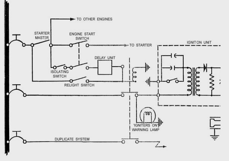
IGNITION SYSTEM
High Energy Ignition Unit
A 12 joule unit receives electrical power from the aircraft d.c. supply either in conjunction with starter operation or independently through the “relight” circuit. An induction coil or transistorized H.T. generator repeatedly charges a capacitor in the unit until the capacitor voltage is sufficient to break down a sealed discharge gap. The discharge is conducted through a choke and H.T. lead to the igniter plug where the energy is released in a flashover on the semiconducting face of the plug. The capacitor is then recharged and the cycle repeated approximately twice every second.
A resistor connected from the output to earth ensures that the energy stored in the capacitor is discharged when the d.c. supply is disconnected.
NOTE: A 3 joule unit is usually supplied with LT alternating current but its function is similar to that described above.
The electrical energy stores in the high energy ignition unit is potentially lethal and even though the capacitor is discharged when the d.c. supply is disconnected, certain precautions are necessary before handling the components. The associated circuit breaker should be tripped, or fuse removed as appropriate, and at least one minute allowed to elapse before touching the ignition unit, high tension lead or igniter plug.
Ignition units are attached to the aircraft structure by anti-vibration mounting and the rubber bushes should be checked for perishing at frequent intervals. It is also important that the bonding cable is securely attached, making good electrical contact and of sufficient length to allow for movement of the unit on its mounting. At the intervals specified in the appropriate Maintenance Schedule the unit should be inspected for signs of damage, cracks or corrosion. Bonding leads securely attached and locked.
Igniter Plug
The igniter plug consists of a central electrode and outer body, the space between them being filled with an insulating material and terminating at the firing end in a semi-conducting pellet. A spring-loaded contact button is fitted at the outer end of the electrode. During operation a small electrical leakage from the ignition unit is fed through the electrode to the plug body and produces an ionized path across the surface of the pellet. The high intensity discharge takes place across this low-resistance path.
Ignition Lead
The high energy ignition lead is used to carry the intermittent high voltage outputs from the ignition unit to the associated igniter plug. A single insulated core is encased in a flexible metal sheath and terminates in a spring-loaded contact button at each end. The end fittings usually incorporate a self locking attachment nut.

IGNITITOR PLUG AND IGNITION LEADS
Relighting
The jet engine requires facilities for relighting should the flame in the combustion system be extinguished during flight. However, the ability of the engine to relight will vary according to the altitude and forward speed of the aircraft.
Within the limits of the envelope, the airflow through the engine will rotate the compressor at a speed satisfactory for relighting; all that is required therefore, provided that a fuel supply is available, is the operation of the ignition system. This is provided for by a separate switch that operates only the ignition system.
Sequence of Starting of Gas Turbine Engine
GROUND RUNNING
The life of a turbine engine is affected both by the number of temperature cycles to which it is subjected and by operation in a dusty or polluted atmosphere. Engine running on the ground should therefore be confined to the following occasions:
-
After engine installation.
-
To confirm a reported engine fault.
-
To check an aircraft system.
-
To prove an adjustment or component change.
-
To prove the engine installation after a period of idleness.
Safety Precautions
Turbine engines ingest large quantities of air and eject gases at high temperature and high velocity, creating danger zones both in front of and behind the aircraft. The extent of these danger zones varies considerably with engine size and location and this information is given in the appropriate aircraft Maintenance Manual. The danger zones should be kept clear of personnel, loose debris and equipment whenever the engines are run. The aircraft should be positioned facing into wind so that the engine intakes and exhausts are over firm concrete with the jet efflux directed away from other aircraft and buildings. Silencers or blast fences should be used whenever possible for runs above idling power.
Additional precautions, such as protective steel plates or deflectors, may be required when testing thrust reversers or jet lift engines, in order to prevent ground erosion. Air intakes and jet pipes should be inspected for loose articles and debris before starting the engine and the aircraft main wheels chocked fore and aft. It may be necessary to tether vertical lift aircraft if a high power check is to be carried out.
Usually on large aircraft one member of the ground crew is stationed outside the aircraft and provided with a radio headset connected to the aircraft intercom system. This crew member is in direct communication with the flight deck and able to provide information and if necessary warnings on situations not visible from inside the aircraft. Due to the high noise level of turbine engines running at maximum power, it is advisable for other ground crew members to wear ear muffs
A suitable CO2 or foam fire extinguisher must be located adjacent to the engine during all ground runs. The aircraft fire extinguishing system should only be used in the event of a fire in an engine which is fully cowled.
Starting
There are many different types of turbine engine starters and starting systems, therefore it is not possible to give a sequence of operations exactly suited to all aircraft. The main requirements for starting are detailed in the following paragraphs.
An external electrical power supply is often required and should be connected before starting. Where a ground/ flight switch is provided this must be set to ‘ground’ and all warning lights checked for correct operation. Where an air supply is required for starting this should be connected and the pressure checked as being sufficient to ensure a start.
NOTE: If the electrical and air supplies are not adequate for starting purposes it is possible for a light-up to occur at insufficient speed for the engine to accelerate under its own power. This could result in excessive turbine temperatures and damage to the engine. The controls and switches should be set for engine starting, a check made to ensure that the area both in front of and behind the engine is clear and the starter engaged. When turbine rotation becomes apparent the HP cock should be opened and the engine instruments monitored to ensure that the starting cycle is normal. When light-up occurs and the engine begins to accelerate under its own power, switch off the starter. If it appears from the rate of increase in exhaust or turbine gas temperature that starting limits will be exceeded the HP cock should be closed immediately and the cause investigated (see under ‘Trouble Shooting’ in the appropriate Maintenance Manual).
Once engine speed has stabilised at idling, a check should be made that all warning lights are out, the external power supplies disconnected and the ground/flight switch moved to ‘flight’.
Testing
When a new engine has been installed a full ground test is necessary, but on other occasions only those parts of the test necessary to satisfy the purpose of the run need be carried out. The test should be as brief as possible and for this reason the aircraft Maintenance Manual specifies a sequence of operations which should always be observed. Records of the instrument readings obtained during each test should be kept to provide a basis for comparison when future engine runs become necessary.
Each aircraft system associated with engine operation should be operated and any warning devices or indicators in the cockpit checked against physical functioning. It may be necessary in certain atmospheric conditions to select engine anti-icing throughout the run and this should be ascertained from the minimum conditions quoted in the Maintenance Manual.
The particular tests related to engine operation are idling speed, maximum speed, acceleration, and function of any compressor airflow controls which may be fitted. Adjustments to correct slight errors in engine operation are provided on the engine fuel pump, flow control unit, and airflow control units. Observed results of the tests must be corrected for ambient pressure and temperature, tables or graphs being provided for this purpose in the aircraft Maintenance Manual. Adjustments may usually be carried out with the engine idling unless it is necessary to disconnect a control.
In this case the engine must be stopped and a duplicate inspection of the control carried out before starting it again. An entry must be made in the engine log book quoting any adjustments made and the ambient conditions at the time.
Stopping
After completion of the engine run the engine should be idled until temperatures stabilise and then the HP cock closed. The time taken for the engine to stop should be noted and compared with previous times, due allowance being made for wind velocity (e.g. a strong head wind will appreciably increase the run-down time). During the run-down fuel should be discharged from certain fuel component drains and this should be confirmed. A blocked drain pipe must be rectified.
When the engine has stopped, all controls and switches used for the run must be turned off and the engine inspected for fuel, oil, fluid and gas leaks. After a new engine has been tested the oil filters should be removed and inspected and after refitting these items the system should be replenished as necessary.
Lubrication System
The lubrication requirements of an aircraft gas turbine engine are generally not too difficult to meet, because the oil does not lubricate any parts of the engine that are directly heated by combustion. Because of this, the loss of oil from the system is small compared with that from a piston engine.
The requirements of a turbo-propeller engine are a little more-severe than those of a turbojet engine, because of the heavily loaded propeller reduction gears and the need for a high pressure oil supply to operate the propeller pitch control mechanism.
Most gas turbine engines use a self-contained recirculatory oil system, in which the oil is distributed and returned to the oil tank by pumps. Some turbojet engines, however, use another system known as the total loss or expendable system in which the oil is spilled overboard after the engine has been lubricated.
Recirculatory are divided into two types they are
-
Pressure Relief Valve
-
Full flow systems,
the major difference between them being in the control of the oil flow to the bearings.
Recirculatory system
Pressure relief valve system
In pressure relief valve system the oil flow to the bearings of the rotating assemblies is controlled by limiting the maximum pressure in the feed line. This is achieved by a system relief valve in which feed oil pressure is opposed by a spring pressure plus atmospheric pressure via the oil tank. On some installations bearing housing pressure or an equivalent of this is used in place of atmospheric pressure. Above a specific engine speed, feed oil pressure overcomes the opposing pressure and the excess oil spills back to the tank, thus maintaining the pressure and flow to the bearings constant at higher engine speeds.
Operation
The pressure pump draws the oil from the tank through strainer which protects the pump gears from any debris which may have entered the tank. Oil is then delivered through a pressure filter to a relief valve (system relief valve) that controls the maximum pressure of the oil flow to the rotating assemblies. On some engines an additional relief valve (pump relief valve) is fitted at the pressure pump out let. This valve is set to open at a much higher pressure than the system relief valve and opens only to return the oil to the inlet side of the pump should the system become blocked. To prevent oil starvation when the oil is very cold or the pressure filter is partially blocked, a bypass valve that operates at a preset pressure difference is fitted across the inlet and outlet of the pressure filter.
On the turbojet system the pressure oil from the relief valve is delivered, through transfer tubes and passages, to lubricate the bearings and gears. Twin-spool engines are provided with a separate metering pump that supplies a controlled amount of oil to the front bearing of the low pressure compressor. This prevents flooding during the initial stage of the starting cycle when only the high pressure compressor is rotating. As the low pressure compressor starts to rotate, oil is supplied to the front bearing, the flow being centred in relationship to compressor speed.
On the turbo-propeller system, the pressure oil is divided after leaving the relief valve, to feed the rotating assembly bearings, propeller pitch control supply system, reduction gear and torque-meter system.
The rotating assembly bearings and some of the heavier loaded gears in the gearboxes are lubricated by oil jets and these are often protected by thread-type filters. The remaining bearings and gears are splash lubricated. Bearings at ‘hot’ end of the engine receive the maximum oil flow because, in addition to lubricating the bearings, the oil assists in heat dissipation.
On some engines, to minimize the effect of the dynamic loads transmitted from the rotating assemblies to the bearing housing, ‘squeeze film’ type bearings are used. These have a small clearance between the outer track of the bearing and the housing, the space being filled with feed oil. The film modifies the radial motion of the rotating assembly and the dynamic loads transmitted to the bearing housing, thus reducing the vibration level of the engine and the possibility of damage by fatigue.
To prevent the flooding of the bearing housing, it is necessary to use more than one pump to return or scavenge it to the oil tank. This is achieved by using a pack of pumps, each of which returns the oil from a particular section of the engine. To protect the pump gears, each return pipe is provided with a strainer that, during inspection, can reveal the failure or impending failure of a component.
Centrifugal breather
To separate the air from the oil returning to the tank, a de-aerating device and a centrifugal breather are incorporated. The return air/oil mixture is fed on to the de-aerator where partial separation occurs, the remaining air/oil mist then passes into the centrifugal breather for final separation. The rotating vanes of the breather centrifuge the oil from the mist and the air is vented overboard through the hollow drive shaft.
Oil coolers
On all engines using the recirculatory type of oil system, heat is transferred to the oil from the engine and it is, therefore, common practice to fit an oil cooler. The cooling medium may be fuel or air and, in some instances, both fuel-cooled and air-cooled coolers are used.
If fuel is used as a cooling medium, either low pressure or high pressure fuel may be used, for in both instances the fuel temperature is much lower than the oil temperature. Whether the cooler is located in the feed side or the return side of a lubrication system depends upon the operating temperature of the bearings.
A turbo-propeller engine may be fitted with an oil cooler that utilizes the external airflow as a cooling medium. This type of cooler, however, incurs a large drag factor and, as kinetic heating of the air occurs at high forward speeds, it is unsuitable for turbojet engines.
Magnetic plugs
Magnetic plugs or chip detectors be fitted in the return oil side of a system to provide a warning of impending failure without having to remove and inspect the scavenge strainers. Some of these detectors are designed so that they can be removed for inspection without oil loss occurring; others may be checked externally by a lamp and battery or even connected to a crew compartment warning system to give an in-flight indication.

MAGNETIC PLUG
Full Flow System
The full flow system is different from a pressure relief valve system, in that the flow of oil to the bearings is determined by the speed of the pressure pump, the size of the oil jets and the pressure in each bearing housing. The system also incorporates a metered spill of feed oil back to the tank and this spill, together with the oil jets, is calibrated to match the pump output.
This arrangement ensures that the oil flow requirements of the bearings are met at all engine speeds. The function of the relief valve in the relief valve system to the open only to prevent excessive oil pressure occurring in the feed side of the system.
A pressure filter bypass valve is not normally fitted, but the pressure drop across either the filter or the system is sensed by a differential pressure switch. An increase in the pressure difference is shown on the indicating system, thus giving advance warning of a blocked filter.
The full flow system, like the pressure relief valve system, draws oil from a tank and delivers it in a similar way, via a pressure filter, to various parts of the engine from where it is returned by scavenge pumps, via oil coolers, to the tank. Likewise, air is separated from the oil by a de-aerator and centrifugal breather.
Magnetic chip detectors are also fitted in the return oil lines, and squeeze film bearings are used to reduce engine vibration; indications of pressure and temperature are also displayed in the crew compartment. On some engines an anti-syphon jet is provided to prevent oil in the feed line draining through the pressure pump into the gearbox when the engine is stationary, the oil being diverted into the oil tank.
Total Loss (Expendable) System
The total loss oil system is generally used only on engines that run for periods of short duration, such as vertical lift and booster engines. The system is simple and incurs low weight penalties, because it requires no oil cooler, scavenge pump or filters. On some engines oil is delivered in a continuous flow to the bearings by a plunger type pump, indirectly driven from the compressor shaft; on others it is delivered by a piston-type pump operated by fuel pressure. On the latter, the oil supply is automatically selected by the high pressure shut-off valve (cock) during engine starting and is delivered as a single shot to the front and rear bearings. On some engines provision is made for a second shot to be delivered to the rear bearing only, after a predetermined period.
After lubricating the fuel unit and front bearings., the oil from the front bearing drains into a collector tray and is then ejected into the main gas stream through an ejector nozzle. The oil that has passed through the rear bearing drains into a reservoir at the rear of the bearing where it is retained by centrifugal force until the engine is shut down. This oil then drains overboard through a central tube in the exhaust unit inner cone.
Lubrication Oils
Gas turbine engines use a low viscosity (thin) synthetic lubricating oil that does not originate from crude oil. The choice of a lubricating oil is initially decided by the loads and operating temperatures of the bearings and the effect that the temperature will have on the viscosity of the oil. Special laboratory and engine tests are then done to prove the suitability of a particular oil for a specific engine and assess the extent to which it deteriorates and the corrosive effects it may have on the engine.
The viscosity of a fluid is its resistance to flow and is measured in stokes, a hundredth part of which is a centistoke. This measurement gives a relationship between the specific gravity of the fluid and the force required to move a plane surface of one square centimetre area over another plane surface at the rate of one centimetre per second, when the two surface are separated by a layer of the test fluid one centimetre thick.
The turbojet engine is able to use a low viscosity oil due to the absence of reciprocating parts and heavy duty gearing. This reduces the power requirement for testing, particularly at low temperatures. Turbo-propeller engines, however, require a slightly higher viscosity oil due to the reduction gear and propeller pitch change mechanism.
All gas turbine oils must retain their lubricating properties and be resistant to oxidation at high temperatures. There are many types of synthetic gas turbine oil and these are manufactured to rigid specifications, but only those specified by the engine manufacturer must be used .
Air-Cooling of Turbine Engines
An important feature in the design of a gas turbine engine is the need to ensure that certain parts of the engine, and in some instances certain accessories, do not absorb heat from the gas stream to an extent that is detrimental to their safe operation. This is achieved by allowing a controlled amount of air from the compressors to flow around these components. The internal cooling airflow is also used to cool the oil, and to pressurize the main bearing housing and various drive shaft seals to maintain the efficiency of the lubrication system by preventing oil leakage. External cooling of the engine power plant is also essential to prevent the transfer of heat to the aircraft structure.

JET ENGINE COOLING SYSTEM
Types of Cooling
Internal cooling
The heat transferred by the turbine blades from the main gas stream to the turbine discs, the bearings of the rotating assemblies, and the engine main casings, is absorbed and dispersed by directing a flow of comparatively cool air over these components. High and low pressure airflows are provided by taking air from both compressors; on completion of its function, the air is either vented overboard or joins the exhaust gas flow.
On the type of engine shown in figure, low pressure (L.P.) air is directed forward to cool the L.P. compressor shaft, and rearward to cool the high pressure (H.P.) compressor shaft L.P. air is also taken from the by-pass duct and fed to the rear of the engine to cool the turbine shafts; the separate L.P. airflows then mix and are ducted overboard after cooling the outer surface of the H.P. turbine shaft. An intermediate H.P. compressor flow is used to cool the rear half of the H.P. compressor shaft and the rear face of the final compressor disc before passing through tubes into the bypass duct.
The H.P. compressor outlet air is directed rearwards onto the turbine discs and, because the flow moves outwards across the discs into the exhaust gas flow, the hot exhaust gases, being of a lower pressure, are prevented from the flowing inwards. The outward flow of cooling air is controlled by inter stage air seals of multi-groove construction that provide the faces of the turbine discs with an adequate cooling airflow. The inter stage air seals are formed in two sections; the front section forms the least restriction, the pressure difference across it being less than that across the rear section. This prevents any inward flow of exhaust gases across the seals.
Due to the high temperature of the gas stream at the turbine inlet, it is often necessary to provide internal air cooling of the nozzle guide vanes and, some instances, the turbine blades. Turbine blade life will depend not only on the form of the cooled blade, but also the method of cooling; therefore, the flow design of the blade internal passages is important.
Recent development of turbine blade cooling is to provide an efficient axial flow of cooling air directly into the blade instead of a pressure feed through the inter stage; this is known as pre-swirl feed.
A variation in temperature of the cooling air will give some indication of engine distress, either by a thermal switch operating a warning indicator at a predetermined temperature of through a thermocouple system to a temperature gauge.
Accessory cooling
A considerable amount of heat is produced by some of the engine accessories, of which electrical generator is an example, and these may often require their own cooling circuit. Air is sometimes ducted from intake louvres in the engine cowlings or it may be taken from a stage of the compressor.
When an accessory is cooled during flight by atmospheric air passing through louvres, it is usually necessary to provide an induced circuit for use during static ground running, when there would be no external air flow. This is achieved by allowing compressor delivery air to pass through nozzles situated in the cooling air outlet duct of the accessory. The air velocity through the nozzles creates a low pressure area which forms an ejector, so inducting a flow of atmospheric air through the intake louvres. To ensure that the ejector system operates only during ground running, the flow of air from the compressor is controlled by a pressure control valve. This valve is electrically opened by a switch that is operated when the weight of the aircraft is supported by the undercarriage.
External cooling and ventilation
The engine bay or pod is usually cooled by atmospheric air being passed around the engine and then vented over board. Conventional cooling during ground running may be provided by using an internal cooling outlet vent as an ejector system. An important function of the cooling air flow is to purge any inflammable vapours from the engine compartment.
By keeping the airflow minimal, the power plant drag is minimized and, as the required quantity of fire extinguishant is in proportion to the zonal airflow . Any fire outbreak would be of low intensity.
A fireproof bulkhead is also provided to separate the ‘cool’ area or zone of the engine, which contains the fuel, oil, hydraulic and electrical systems, from the ‘hot’ area surrounding, the combustion, turbine and exhaust sections of the engine. Differential pressures can be created in the two zones by calibration of the inlet and outlet apertures to prevent the spread of fire from the hot zone.
Fuel System
The functions of the fuel system are to provide the engine with fuel in a form suitable for combustion and to control the flow to the required quantity necessary for easy starting acceleration and stable running, at all engine operating conditions, to do this, one or more fuel pumps are used to deliver the fuel to the fuel spray nozzles, which inject it into the combustion system in the form of an atomized spray because the flow rate must vary according to the amount of air passing through the engine to maintain a constant selected engine speed or pressure ratio, the controlling devices are fully automatic with the exception of engine power selection, which is achieved by a manual throttle or power lever.
A fuel shut-off valve (cock) control lever is also used to stop engine, although in some instances these two manual controls are combined for single-lever operation.
It is also necessary to have automatic safety controls that prevent the engine gas temperature, compressor delivery pressure, and the rotating assembly speed, from exceeding their maximum limitations.
With the turbo-propeller engine, changes in propeller speed and pitch have to be taken into account due to their effect on the power output of the engine. Thus, it is usual to interconnect the throttle lever and propeller controller unit, for by so doing the correct relationship between fuel flow and airflow is maintained at all engine speeds and the pilot is given single-lever control of the engine. Although the maximum speed of the engine is normally determined by the propeller speed controller, over speeding is ultimately prevented by a governor in the fuel system.
Fuel system also provides oil cooling for lubricating system of various engine parts.
There are two types of fuel control i.e. Automatic and Manual. Automatic control system is divided into 3 parts they are :
-
Pressure Control System
-
Flow control system
-
Acceleration and speed control.
Some engines are fitted with an electronic system of control and this generally involves the use of electronic circuits to measure and translate changing engine condition to automatically adjust the fuel pump output. On helicopters powered by gas turbine engines using the free power turbine principle, additional manual and automatic controls on the engine govern the free power turbine and consequently aircraft rotor speed.
Fuel Control System
Typical high pressure (H.P.) fuel control systems for a turbo-propeller engine and a turbojet engine are shown in simplified form in figure 1, each basically consisting of an H.P. pump, a throttle control and a number of fuel spray nozzles, In addition, certain sensing devices are incorporated to provide automatic control of the fuel flow in response to engine requirements. On the turbo-propeller engine, the fuel and propeller systems are coordinated to produce the appropriate fuel/r.p.m. combination.
The usual method of varying the fuel flow to the spray nozzles is by adjusting the output of the H.P. fuel pump. This is effected through a servo system in response to some or all of the following :
-
Throttle Movement
-
Air, temperature and pressure
-
Rapid acceleration and deceleration
-
Signals of engine speed, engine gas temperature and compressor delivery pressure
Fuel Pump
On some early turbine engines a constant displacement pump was used, the design of which ensured that pump delivery was always in excess of engine requirements. Excess fuel was bled back to the fuel tanks by means of unit called a Barostat which was sensitive to changes in air intake pressure. Most modern British systems employ a pump of the variable stroke (swash-plate) type, a dual pump often being fitted on large engines to obtain high delivery rates.
The variable stroke pump is driven directly from the engine and consists of rotating cylinder block in which a number of cylinders are arranged around the rotational axis. A spring-loaded piston in each cylinder is held against a nonrotating cam plate so that rotation of the cylinder block results in the pistons moving up and down in their respective cylinders. Conveniently placed ports in the pump body allow fuel to be drawn into the cylinders and discharged to the engine. The angle of the cam plate determines the length of stroke of the piston and, by connecting it to a servo mechanism, delivery may be varied from the nil to maximum pump capacity for a given pump speed.
The servo piston operates in a cylinder and is subjected to pump delivery pressure on one side and the combined forces of reduced delivery (servo) pressure and a spring on the other. A calibrated restrictor supplies pump delivery fuel to the spring side of the piston and this is bled off by the control system to adjust the piston position and hence the angle of the cam plate.
Fuel Pump Control System
Some engines are fitted with a control system which uses electronic circuits to sense changing fuel requirements and adjust pump stroke. Most engines however, use hydro-mechanical systems, with an electromechanical element to control maximum gas temperature and these are discussed in the following paragraphs.
Pressure controller
The quantity of fuel passing through a restrictor (the throttle valve may be varied by increasing or decreasing the fuel pressure. In the pressure control system fuel pressure is varied in relation to air intake pressure, decreasing with decreased mass air flow through the engine, Spill valves in the Barometric Pressure Control (B.P.C), Acceleration Control Unit (A.C.U.) and pump governor, bleed off servo pressure to control pump stroke.
Under steady running conditions below maximum governed speed only the B.P.C. spill valve is open. A capsule subject to air intake pressure, contained in the B.P.C., controls the extent to which the spill valve is open. The bleed is arranged to increase as intake pressure decreases thus reducing servo pressure, pump stroke and fuel delivery pressure as altitude increases.
When the throttle is opened slowly, reduced throttle inlet pressure is transmitted to the B.P.C. and the spill valve closes to increase servo pressure and pump stroke. As pressure to the throttle is restored the B.P.C. spill valve again takes up its controlling position, and pump stroke, combined with increased pump speed, stabilises to give the output for the new throttle position. If the aircraft is in level flight the increasing speed will increase intake pressure and act on the B.P.C. capsule to further increase fuel flow to match the increasing mass air flow.
During rapid throttle opening, the action of the B.P.C. spill valve closes, increased fuel flow creates an increased pressure drop across the Metering Valve which is sensed by the A.C.U. fuel diaphragm. Movement of this diaphragm opens the A.C.U. spill valve to reduce servo pressure and limit over fuelling to the maximum amount which can be tolerated by the engine. As the engine accelerates, increasing compressor delivery pressure acting on the A.C.U. air diaphragm gradually closes the spill valve to permit greater acceleration at higher engine speeds.
Radial drilling in the fuel pump rotor direct fuel under centrifugal force to one side of a spring loaded diaphragm in the governor unit. When centrifugal force reaches a predetermined value the diaphragm flexes sufficiently to open its spill valve and reduce servo pressure, thus limiting the amount of fuel delivered to the engine and so controlling engine speed.
Flow control
In this system fuel pump delivery is controlled to maintain a constant pressure drop across the throttle valve regardless of engine speed A common variation of the system is one in which a small controlling flow (proportional flow) is created with the same characteristics as the main flow and is used to adjust the main flow. A different type of spill valve known as a “kinetic” valve is used which consists of opposing jets of fuel at pump delivery pressure and servo pressure; a blade moving between the jets alters the effect of the high pressure on the low pressure. When the blade is clear of the jets, servo pressure is at maximum and moves the fuel pump to maximum stroke but as the blade comes between the jets servo pressure reduces to shorten pump stroke. The control elements which are housed in a single unit called the Fuel Control Unit (F.C.U.) and throttle, which sometimes also functions as a shut-off (H.P.) cock. the system.
Under steady running conditions below governed speed, flow through two P.V.U. restrictors is proportional to flow through the throttle valve and the P.V.U. diaphragm is held open by spring pressure, allowing fuel to flow through the A.S.U. back to the pump inlet. The A.S.U. adjusts servo pressure in relation to this proportional flow by means of a kinetic spill valve.
When the throttle is opened slowly the pressure drop across and throttle valve and P.V.U. restrictors decreases and the P.V.U. diaphragm adjusts its position to reduce proportional flow through the A.S.U. This results in the A.S.U. spill valve closing slightly to increase servo pressure and therefore pump stroke, thus restoring the pressure difference across the throttle and P.V.U. restrictors.
Variation in air intake pressure are sensed by a capsule in the A.S.U. which adjusts its spill valve to decrease or increase servo pressure as required. The resulting change in proportional flow returns the A.S.U. spill valve to its controlling position.
During rapid throttle opening the sudden decrease in pressure drop across the throttle is sensed by the A.S.U. which closes its spill valve to increase pump stroke. The rapid increase in fuel flow, which would cause over fuelling, is restricted by means of a pressure drop diaphragm and metering plunger. This diaphragm is sensitive to the pressure drop across the metering plunger, the latter being located in the main fuel line to the throttle valve. Rapid throttle opening increases the pressure drop across the plunger and at a fixed rate of over fuelling the pressure drop diaphragm flexes sufficiently to open its spill valve and override the A.S.U. , maintaining a fixed pressure drop across the metering plunger.
The metering plunger is, in effect, a variable area orifice and by means of a capsule in the A.C.U. sensitive to compressor delivery pressure, its position is controlled, over fuelling and engine speed increase, the pressure drop across the throttle valve is gradually restored until the proportional flow reaches a controlling value once more and the A.S.U. spill valve controls pump stroke.
Fuel under centrifugal force from the fuel pump also acts on a diaphragm in the P.V.U. to adjust the position of one of the restrictions and maintain proportional flow at a value suitable for idling.
Combined acceleration and speed control
This fuel pump control system is contained within a single unit called a Fuel Flow Regulator, the fuel pump servo piston being operated by fuel pump delivery pressure opposed by main burner pressure and a spring.
Two rotating assemblies, each with a hollow valve and centrifugal governor, are driven from the engine by a gear train in the regulator and are known as the Speed Control Unit and the Pressure Drop Unit. The speed control valve is given axial movement by a capsule assembly under compressor delivery pressure and has a triangular hole known as the Variable Metering Orifice (V.M.O.). A non rotating governor sleeve round this valve is given axial movement by the governor unit and restricts fuel flow through the V.M.O. Fuel from the pump outlet flows from the regulator body through the V.M.O. to the inside of the speed control valve and passes through the hollow valve to the pressure drop unit. The pressure drop valve is in the form of a hollow piston, moving axially under the force of fuel from the V.M.O. and governor flyweights, has an unrestricted outlet through the regulator body for primary burner fuel and a triangular outlet known as the Pressure Drop Control Orifice (P.D.C.O.) through which fuel flow to the main burners is restricted by the axial movement of the pressure drop valve.
Under steady running conditions the position of the speed control valve is fixed by the capsule assembly and the governor sleeve is held in a fixed axial position, the drop valve which adjusts its position and the exposed area of the P.D.C.O. to supply the correct quantity of fuel in relation to engine speed.
When the throttle is opened slowly, spring loading on the speed control governor increases to move the governor sleeve and increase the V.M.O. area. Pressure drop across the V.M.O. decreases and this is sensed by the pressure drop valve which moves to increase the size of the P.D.C.O. the reduced system pressure difference acting on the pump servo piston to increase fuel flow to the engine. As the engine accelerates, the capsule in the speed control unit is compressed due to compressor delivery pressure and moves the speed control valve to further increase the size of the V.M.O. Balance is restored when centrifugal force acting on the speed control governor moves the governor sleeve to restore the system pressure difference.
The effect to rapid throttle movements is restricted by mechanical stops acting on the governor sleeve. Changes in altitude or forward speed affect the capsule of the speed control unit which adjusts the position of the speed control valve to correct fuel flow.
Burners
The purpose of the burners is to provide fuel to the engine in a suitable form for combustion. A burner with a single spray nozzle, although used on some early engines, is not suitable for large modern engines due to the widely varying fuel flow requirements for different flight conditions.
If the orifice were of the size suitable for atomising fuel at low rates of flow the pressure required at take-off would be tremendously high, flow through an orifice being proportional to the square of the pressure drop across it.
One of the methods used to overcome this problem is the provision of a dual spray burner. The central orifice provides the fuel for low flow rates and a second annular orifice is used in addition for high flow rates. Distribution between the primary (low flow) manifold and the main (high flow) manifold is normally controlled by a pressure operated valve. In the case of the Fuel flow Regulator, fuel flowing through the rectangular outlet from the pressure drop valve is always at a higher pressure than fuel flowing through the outlet from the P.D.C.O. and is used to supply the primary burner manifold.
Another method used on some engines is known as the Vaporising Burner. Fuel is injected at low pressure into one end of a hollow “U” shaped tube located in the combustion chamber. It mixes with the primary air flow, is vaporised by the heat in the chamber and ejected upstream into the combustion zone. In this system a separate burner is necessary for engine starting.
Additional Controls
Turbine gas temperature control
Control of the maximum permitted turbine gas temperature is often exercised electrically. Signals from the T.G.T. thermocouples are amplified to either actuate a solenoid operated valve in the fuel system or reset the throttle linkage to reduce fuel flow to the burners. On engines which have different T.G.T. limitations for climb and take-off, a switch on the flight deck pre-sets the T.G.T. signal reference datum.
Compressor control
In certain circumstances such as high forward speed and low ambient temperature it is possible to produce maximum power/thrust at less than maximum engine speed. Under these conditions the engine could sustain damage due to high compressor delivery pressures and fuel flow is restricted by providing a bleed from the A.C.U. capsule, chamber to atmosphere when compressor delivery pressure exceeds a predetermined value.
To prevent the low pressure compressor from exceeding its design speed a centrifugal governor driven from the low pressure shaft is often included in the fuel system. If design speed is exceeded the low pressure governor restricts the fuel flow in the main burner line and reduces both high and low pressure compressor speeds.