
HYDRAULIC SYSTEM
Introduction
Hydraulics is a method of transmitting power through pipes and control devices, using liquid as the operating medium.
For certain applications hydraulic systems are used in preference to mechanical or electrical systems for a number of reasons, among which are ease of application of force, ability to increase the applied force as necessary, ease of routing of pipelines, and elimination of backlash between components.
Hydraulic systems provide the power for the operation of components such as landing gear, flaps, flight controls, wheel brakes, windshield wipers and other systems that require high power, accurate control and rapid response rates.
Pascal’s Law
Pascal was a 17th century mathematician who stated that:
“If a force is applied to a liquid in a confined space, then this force will be felt equally in all directions”.
The force employed when a hydraulic system is operated is caused by “Pressure”.
This force is not delivered by the hydraulic pump. Hydraulic pressure is created only when an attempt is made to compress fluids, therefore, if a flow of oil is pumped through an open- ended tube there will be no pressure, but, if the end of the tube is blocked and the oil cannot escape, pressure will at once build up.
Bramah’s Press
This principle was discovered by Joseph Bramah (1749 - 1814) who invented a hydraulic press and, in doing so, observed two facts:
-
the smaller the area under load, the greater the pressure generated.
-
the larger the area under pressure, the greater will be the load available.
Liquids are, for most practical purposes, incompressible, and this fact enables movement to be transmitted through pipelines, over great distances, without loss of time or motion. However, liquids will expand or contract as a result of temperature changes, and a relief valve is necessary, to prevent damage from excessive pressures, in any closed system which may be subjected to large changes of temperature.
In a closed static system, pressure exerted on a liquid is transmitted equally in all directions.

ADVANTAGE OF USING HYDRAULIC
The area of piston A is 10 mm2, and the force applied to it is 10N,. The pressure in the liquid is, therefore, 10N/mm2, which is transmitted undiminished to piston B. The area of piston B is 100mm2 , and the force exerted upon it is thus 100N, representing a mechanical advantage of 10:1. This advantage is obtained at the expense of distance, however, because the area of piston B is 10 times that of piston A and piston B will move only one tenth the distance of piston A.
When liquid is in motion, its dynamic characteristics must also be taken into consideration. Friction exist between the molecules of a liquid, and between the liquid and the piping through which it flows; this friction increases with any increase in viscosity or velocity of the liquid. Friction results in some of the power available from a pump being transformed into heat, and in a reduction in pressure throughout the pipelines.
Any restriction in a pipeline will increase liquid velocity and produce turbulence, resulting in reduced
pressure downstream of the restriction. This fact is often exploited in system design and a restrictor is also
used to limit the rate of liquid flow, and thus the rate of movement of components such as the landing gear
or flaps.
Hydraulic Fluid
Almost any sort of liquid could be used in a hydraulic system, but the special requirements of aircraft systems have resulted in the use of vegetable, mineral and synthetic-based oils (known as hydraulic fluids) which have the following properties :-
-
They provide good lubrication of components.
-
Their viscosity is low enough to minimise friction in pipelines and to allow high-speed operation of motors and pumps, but high enough to prevent leakage from components.
-
They prevent internal corrosion in the system.
-
They have a wide operating-temperature range.
Let us look at some of the properties in details
Viscosity
One of the most important properties of any hydraulic fluid is its viscosity. Viscosity is internal resistance to flow. A liquid such as gasoline that has a low viscosity flows easily, while a liquid such as tar that has a high viscosity flows slowly. Viscosity increases as temperature decreases. A satisfactory liquid for a given hydraulic system must have enough body to give a good seal at pumps, valves, and pistons, but it must not be so thick that it offers resistance to flow, leading to power loss and higher operating temperatures. These factors add to the load and to excessive wear of parts. A fluid that is too thin also leads to rapid wear of moving parts or of parts that have heavy loads. The instruments used to measure the viscosity of a liquid are known as viscometers. Several types of viscometers are in use today. The Saybolt viscometer measures the time required, in seconds, for 60 milliliters of the tested fluid at 100 °F to pass through a standard orifice. The time measured is used to express the fluid’s viscosity, in Saybolt universal seconds or Saybolt FUROL seconds
Chemical Stability
Chemical stability is another property that is exceedingly important in selecting a hydraulic liquid. It is the liquid’s ability to resist oxidation and deterioration for long periods. All liquids tend to undergo unfavorable chemical changes under severe operating conditions. This is the case, for example, when a system operates for a considerable period of time at high temperatures. Excessive temperatures have a great effect on the life of a liquid.
It should be noted that the temperature of the liquid in the reservoir of an operating hydraulic system does not always represent a true state of operating conditions. Localized hot spots occur on bearings, gear teeth, or at the point where liquid under pressure is forced through a small orifice. Continuous passage of a liquid through these points may produce local temperatures high enough to carbonize or sludge the liquid, yet the liquid in the reservoir may not indicate an excessively high temperature.
Liquids with a high viscosity have a greater resistance to heat than light or low-viscosity liquids that have been derived from the same source. The average hydraulic liquid has a low viscosity. Fortunately, there is a wide choice of liquids available for use within the viscosity range required of hydraulic liquids.
Liquids may break down if exposed to air, water, salt, or other impurities, especially if they are in constant motion or subject to heat. Some metals, such as zinc, lead, brass, and copper, have an undesirable chemical reaction on certain liquids. These chemical processes result in the formation of sludge, gums, and carbon or other deposits that clog openings, cause valves and pistons to stick or leak, and give poor lubrication to moving parts. As soon as small amounts of sludge or other deposits are formed, the rate of formation generally increases more rapidly. As they are formed, certain changes in the physical and chemical properties of the liquid take place. The liquid usually becomes darker in color, higher in viscosity, and acids are formed.
Flash Point
Flash point is the temperature at which a liquid gives off vapor in sufficient quantity to ignite momentarily or flash when a flame is applied. A high flash point is desirable for hydraulic liquids because it indicates good resistance to combustion and a low degree of evaporation at normal temperatures.
Fire Point
Fire point is the temperature at which a substance gives off vapor in sufficient quantity to ignite and continue to burn when exposed to a spark or flame. Like flash point, a high fire point is required of desirable hydraulic liquids.
Types of Hydraulic Fluids
Fluids are colored for recognition purposes, and fluids to different specifications must never be mixed; fluids to the same specification, but produced by different manufacturers, may be mixed when permitted by the appropriate Maintenance Manual. Use of a fluid which is not approved for a particular system may result in rapid deterioration of seals, hoses and other nonmetallic parts, and may render the system inoperative.
-
Vegetable-based fluid is normally almost colorless, and must be used with pure rubber seals and hoses. It is used in some braking systems, but is not often found in hydraulic power systems.
-
Mineral-based fluid is normally coloured red, and must be used with synthetic rubber seals and hoses. It is widely used in light aircraft braking systems, hydraulic power systems, and shock-absorber struts.
-
Phosphate ester based fluid is widely used on modern aircraft, mainly because of its fire-resistance and extended operating-temperature range. It may be coloured green, purple or amber, and must only be used with butyl rubber, ethylene propylene or tebblon seals and hoses.
In view of the incompatibility of different fluids, it is important that any containers, or test rigs, used for servicing aircraft, are clearly marked with the type of fluid they contain.
Basic System
There are six main components common to all hydraulic systems:
-
a reservoir of oil, which delivers oil to the pump and receives oil from the actuators.
-
a pump, either hand, engine or electrically driven.
-
a selector or control valve, enabling the operator to select the direction of the flow of fluid to the required service and providing a return path for the oil to the reservoir.
-
a jack, or set of jacks or actuators, to actuate the component.
-
a filter, to keep the fluid clean.
-
a relief valve, as a safety device to relieve excess pressure.
BASIC HYDRAULIC SYSTEM
Reservoir
A reservoir provides both storage space for the system fluid, and sufficient air space to allow for any variations in the volume of fluid in the system which may be caused by thermal expansion and actuator operation. Most reservoirs are pressurized, to provide a positive fluid pressure at the pump inlet, and to prevent air bubbles from forming in the fluid at high altitude. On modern jet aircraft, air pressure is normally supplied from the compressor section of an engine, but it may be supplied from the cabin pressurization system. Air entering the reservoir is filtered, and, in some cases, provision is also made for the removal of moisture.
A reservoir also contains a relief valve, to prevent over pressurization; connections for suction pipes to the pumps, and return pipes from the system; a contents transmitter unit and a filler cap; and, in some cases, a temperature sensing probe. In systems which are fitted with a hand pump, the main pumps draw fluid through a stack pipe in the reservoir. This ensures that, if fluid is lost from that part of the system supplying the main pumps, or supplied solely by the main pumps, a reserve of fluid for the hand pump would still be available.

RESERVOIR
Hydraulic Pumps
Most modern aircraft are fitted with either fixed volume or variable volume, multi-piston type hydraulic pumps, driven from the engines. Other types of pumps, such as gear or vane positive displacement pumps, may be found in some installations, but these are generally used for powering emergency systems. Hand pumps, where fitted, are often of the double-acting type.
Hand Pump
A hand pump is included in some aircraft installations, for emergency use and for ground. servicing operations.
Fig illustrates a double acting hand pump (i.e. a pump which delivers fluid on each stroke). As the piston moves upward in the cylinder, fluids drawn in through a non-return valve (NRV) at the inlet connection into the cylinder; at the same time fluid above the piston is discharged through a non-return valve in the outlet connection.
As the piston moves downwards, the inlet NRV closes and the transfer NRV opens, allowing fluid to flow through the piston; since the area below the piston is larger than the area above the piston, part of this fluid is discharged through the outlet port. When pressure in the outlet line exceeds the relief valve setting, discharged fluid is by- passed back to the pump inlet.

HAND PUMP
Fixed Volume Pumps
These pumps deliver a fixed quantity of fluid into the system at a particular speed of rotation, regardless of system requirements, and means must be provided for diverting pump output when it is not required in the system.
There are many types like
-
axial piston pump
-
gear type pump
-
vane type pumps
Axial Piston Pump
The cylinder block and drive shaft rotate together, and because of the angle between the cylinder block and shaft axes, each piston moves into and out of its cylinder once each revolution. The stationary valve block has two circumferential slots leading to the top of the cylinder block, which are connected to the fluid inlet and outlet ports, and are arranged so that the pistons draw fluid into the cylinders on the outward stroke, and expel fluid into the system on the inward stroke.

AXIAL PISTON PUMP
Gear Type Pump
The gear type power pump consists of two meshed gear that revolve in a housing, the driving gear is driven by aircraft engine or some other power unit, the driven gear meshes with and is driven by driving gear.
Clearance between the both as they mesh and between the teeth and the housing is very small. Inlet port of the pump is connected to the reservoir and the outlet port is connected to the pressure line, when the driving gear turns in anti clockwise direction. As the gear teeth passes the inlet port, fluid is trapped between the gear teeth and housing and is then carried around the housing to the out let port.

GEAR TYPE PUMP
Vane Type Pump
Pump consists of a housing containing four vanes or blades, a hollow steel rotor with slots for the vanes and a coupling to turn the rotor. The rotor is positioned off center within the sleeve. The vanes which are mounted in the slots in the rotor, together with the rotor decide the boar of the sleeve into four sections. As the rotor turns each section in the turn passes one point where its volume at a minimum and another point where its volume is at a maximum.
The volume gradually increases from minimum to maximum during one half of a revolution and gradually decrease from maximum to minimum during the second half of the revolution as the volume of a given section is increasing, that section is connected to the pump inlet port, through a slot in the sleeve. Since a partial vacuum is produced by a increase in volume of the section, fluid is drawn into the section through the pump inlet port and the slot in the sleeve.
As the rotor turns through the second half of the revolution and the volume of the given section is decreasing fluid is displaced out of the section through the slot in the sleeve through the outlet port to the system.

VANE TYPE PUMP
Gerotor Type Pump
A gerotor-type power pump consists essentially of a housing containing an eccentric-shaped stationary
liner, an internal gear rotor having five wide teeth of short height, a spur driving gear having four narrow teeth, and a pump cover which contains two crescent-shaped openings. One opening extends into an inlet port, and the other extends into an outlet port. The pump cover has its mating face turned up to clearly show the crescent-shaped openings. When the cover is turned over and properly installed on the pump housing, it will have its inlet port on the left and the outlet port on the right.
During the operation of the pump, the gears turn clockwise. As the pockets on the left side of the pump
move from a lowermost position toward a topmost position, the pockets increase in size resulting in the production of a partial vacuum within these pockets. As the pockets open at the inlet port, fluid is drawn into them.
As these same pockets (now full of fluid) rotate over to the right side of the pump, moving from the topmost
position toward the lowermost position, they decrease in size. This results in the fluid being expelled from the
pockets through the outlet port.

GEROTOR TYPE PUMP
Variable Volume Pump
This type of pump is similar in construction to the fixed volume pump described in pump described in before, but the cylinder block and drive shaft are co-axial. The pistons are attached to shoes which rotate against a stationary yoke, and the angle between the yoke and cylinder block is varied to increase or decrease pump stroke to suit system requirements.
When pressure in the system is low, as would be the case following selection of a service, spring pressure on the control piston turns the yoke to its maximum angle, and the pistons are at full stroke, delivering maximum output to the system. When the actuator has completed its stroke, pressure builds up until the control piston moves the yoke to the minimum stroke position; in this position a small flow through the pump is maintained, to lubricate the working parts, overcome internal leakage and dissipate heat. On some pumps a solenoid-operated depressurizing valve is used to block delivery to the system, and to off-load the pump.

VARIABLE DISPLACEMENT PUMP
Pressure Control
Maximum system pressure is often controlled by adjustment of the main engine-driven pump, but a number of other components are used to maintain or limit fluid pressures in various parts of a hydraulic system, and these sometimes have additional functions.
Relief Valves
A relief valve is the simplest form of pressure limiting device, and may be used by itself, or within larger components. A relief valve is frequently used as a safety device, e.g. a thermal relief valve, in which case it is adjusted to blow-off at a pressure slightly higher than normal system pressure, and is normally designed to relieve only a small quantity of fluid.
In some systems a full-flow relief valve is fitted downstream of the pump, to by-pass full pump output to the reservoir in the event of failure of the cutout valve, or of blockage elsewhere in the system. A simple ball-type relief valve and full-flow relief valve.

TYPES OF RELIEF VALVES
Cut-Out Valves
A cut-out valve is fitted to a system employing a fixed volume pump, to provide the pump with an idling circuit when no services have been selected. An accumulator is essential when a cut-out is fitted, since any slight leakage through components, or from the system, would result in operation of the cut-out, and in frequent loading and unloading of the pump.

CUT OUT VALVE
When a service has been selected and the pump is delivering fluid to the system, the NRV is open and equal pressure is applied to the poppet valve and piston; the force of the spring combined with the pressure on the poppet valve, is greater than the force on the piston, so the valve is closed and the return line to reservoir is blocked.
When the service selected has completed its travel, pressure builds up in the delivery line to the system until the force applied to the piston is sufficient to lift the poppet valve off its seat; this results in a sudden drop in pressure on the pump side of the poppet valve which snaps the poppet valve open and the NRV closed. Pressure in the return line drops to a low value and the load on the pump is removed.
Pressure in the system is maintained by the accumulator until a further selection is made; when pressure drops, and the force on the cut-out piston becomes less than the spring force, the poppet valve closes and pump output is again directed into the system.
Pressure Maintaining Valves
A pressure maintaining valve, or priority valve, is basically a relief valve which maintains the pressure in a primary service at a value suitable for operation of that service, regardless of secondary service requirements. When main system pressure exceeds this pre-determined value, the spring load is overcome, and the valve opens to allow main system pressure to reach the secondary service.
A pressure maintaining valve is generally used to safeguard operation of important services such as flying controls and wheel brakes. Fig. shows a valve in the open position, pressure being sufficient to move the piston against spring pressure and connect the main supply to the sub-system.

PRESSURE MAINTAINING VALVE
Pressure Reducing Valves
A pressure reducing valve is often used to reduce main system pressure to a value suitable for operation of a service such as the wheel brakes.
Fig illustrates a pressure reducing valve, which also acts as a relief valve for the service operating at reduced pressure. Fluid enters the inlet port, and flows through the valve to the sub-system; when the fluid pressure exceeds the spring-loading on the valve, the valve is lifted and gradually covers the inlet port until subsystem pressure reaches the specified value.
If sub-system pressure increases for any reason, the valve is lifted further and uncovers the return port to relieve excess pressure.

PRESSURE REDUCING VALVE
Brake Control Valves
A brake control valve is essentially a variable pressure reducing valve, which controls pressure in the brake system according to the position of the pilots’ brake pedals. The valve usually contains four elements, one pair for the brakes on each side of the aircraft, to provide duplicated control.
When either pilot’s brake pedal on the appropriate side is depressed, or the hand brake is operated, the servo piston applies load to the linkage on the control valve, which, via the lever assembly and plunger, presses down the exhaust valve cap. This action initially closes the gap between the exhaust valve cap and the exhaust valve, valve seat, then moves the cradle down to open the inlet valve, and to direct fluid to the brakes.
Pressure builds up in the brakes and valve, until it is sufficient, assisted by the spring, to overcome the inlet pressure, to force the cradle and exhaust valve seat against the exhaust valve cap, and to close the inlet valve. An increase in the load applied to the valve linkage will be balanced by increased delivery pressure, and a decrease in the load applied will be balanced by relief of delivery pressure past the exhaust valve. When the brake pedals are released, the exhaust valve cap lifts, and exhausts pressure from the brakes to the reservoir.
Flow Control
They components described in this paragraph are used to control the flow of fluid to the various services operated by the hydraulic system.
Non-return Valves (Check Valves)
The most common device used to control the flow of fluid is the non-return valve, which permits full flow in one direction, but blocks flow in the opposite direction. Simple ball-type non-return valves are included in Fig. but design may vary considerably. When a non-return valve is used as a separate component, the direction of flow is indicated by an arrow moulded on the casing, in order to prevent incorrect installation.
.jpg)
NON RETURN VALVE (NRV) OR CHECK VALVE
Restrictor Valves
A restrictor valve may be similar in construction to a non-return valve, but a restrictor valve is designed to permit limited flow in one direction and full flow in the other direction; the restriction is usually of fixed size, as shown in Fig. A restrictor valve is used in a number of locations, in order to limit the speed of operation of an actuator in one direction only. It may, for instance, be used to slow down flap retraction or landing gear extension.

RESTRICTOR VALVES
Selector Valve
Selector Valves. Selector valves are used to direct fluid to the appropriate side of a jack and connect the other side to return. Some are manually operated but on large transport aircraft they are operated remotely either mechanically or electrically. Selectors are of two main types open centre or closed centre and may be rotary or linear in construction.
Rotary Selectors
Different types of rotary selectors are used depending on the type of actuator. A simple two port selector is used with a single acting actuator. Double acting actuators will use a four port selector. This enables the actuator to be extended by directing fluid to one side of the actuator and open the opposite side to return. The selector can then be rotated to redirect the fluid to retract the actuator.
Linear Slide Selector or Spool Valve Selector. This type of selector is operated by a linear movement and is typically operated mechanically by a rod or cable but may be operated electrically.

DIFFERENT TYPES OF SELECTOR VALVE
It is sometimes necessary to be able to hold the actuator in an intermediate position. On some aircraft this is achieved by using a selector which blocks both lines to the actuator when it is in the neutral position, the selector being manually returned when the desired actuator position is reached. However, as this could be distracting for the pilot at a critical stage of flight, a feedback mechanism is often used, which automatically returns the selector to neutral whenever a selected position is reached.
Electrically-operated Selectors
It is sometimes convenient to locate a selector valve at a position remote from the crew compartment, and to eliminate the need for extensive mechanical linkage the selector is normally operated electrically.
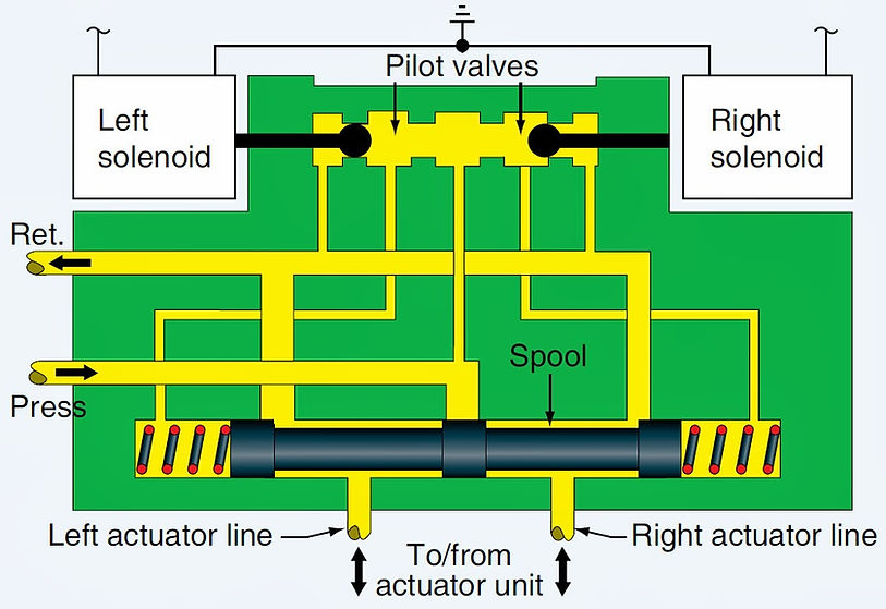
Figure illustrates the internal flow paths of a solenoid operated selector valve. The closed center valve is shown in the NEUTRAL or OFF position. Neither solenoid is energized. The pressure port routes fluid to the center lobe on the spool, which blocks the flow. Fluid pressure flows through the pilot valves and applies equal pressure on both ends of the spool. The actuator lines are connected around the spool to the return line.
.jpg)
ELECTRICAL SELECTOR VALVE
When selected via a switch in the cockpit, the right solenoid is energized. The right pilot valve plug shifts left, which blocks pressurized fluid from reaching the right end of the main spool. The spool slides to the right due to greater pressure applied on the left end of the spool.
The center lobe of the spool no longer blocks system pressurized fluid, which flows to the actuator through the left actuator line. At the same time, return flow is blocked from the main spool left chamber so the actuator (not shown) moves in the selected direction. Return fluid from the moving actuator flows through the right actuator line past the spool and into the return line.
%20Worki.jpg)
ELECTRICAL SELECTOR VALVE WORKING
Typically, the actuator or moving device contacts a limit switch when the desired motion is complete. The switch causes the right solenoid to de-energize and the right pilot valve reopens. Pressurized fluid can once again flow through the pilot valve and into the main spool right end chamber. There, the spring and fluid pressure shift the spool back to the left into the NEUTRAL or OFF position.
To make the actuator move in the opposite direction, the cockpit switch is moved in the opposite direction. All motion inside the selector valve is the same as described above but in the opposite direction. The left solenoid is energized. Pressure is applied to the actuator through the right port and return fluid from the left actuator line is connected to the return port through the motion of the spool to the left.
Shuttle Valve
These are often used in landing gear and brake systems, to enable an emergency system to operate the same actuators as the normal system. During normal operation, free flow is provided from the normal system to the service and the emergency line is blocked. When normal system pressure is lost and the emergency system is selected, the shuttle valve moves across because of the pressure difference, blocking the normal line and allowing emergency pressure to the actuator. A typical shuttle valve is shown in Fig.

SHUTTLE VALVE
Sequence valve
Sequence valves are often fitted in a landing gear circuit to ensure correct operation of the landing gear doors and jacks. Examples of mechanically operated and hydraulically operated sequence valves are illustrated in Fig.
Mechanically operated sequence valves ensure that the landing gear does not extend until the doors are open, and that the landing gear is retracted before the doors close. Completion of the initial movement in the sequence results in part of the mechanism operating the plunger of the sequence valve, and allowing fluid to flow to the next actuator.
During extension of the landing gear, pressure in the ‘up’ lines could exceed pressure in the ‘down’ lines, because of the force of gravity acting on the landing gear, and thus result in partial closing of the doors. This is prevented by fitting a hydraulically operated sequence valve in the ‘up’ line, which blocks return flow until down line pressure, acting on the plunger, is sufficient to overcome the spring and open the valve. The ball valve is virtually a non-return valve, which does not significantly restrict flow when the landing gear is selected up.

SEQUENCE VALVE
Modulator
A modulator is used in conjunction with the anti-skid unit in a brake system. It allows full flow to the brake units on initial brake application, and thereafter a restricted flow.
Fig. shows a modulator, the swept volume of which would be equal to the operating volume of the brake cylinders. During initial operation of the brake control valve, the piston is forced down the cylinder against spring pressure, and the brakes are applied.
Subsequent fluid feed to the brakes, necessitated by anti-skid unit operation, is through the restricting orifice, and is very limited. This limited flow allows the anti-skid unit to completely release the brakes when necessary, and conserves main system pressure. When the control valve is released, the piston returns to its original position under the influence of the spring and the return fluid.

MODULATOR
Flow Control Valves
A flow control valve may be fitted in a hydraulic system to maintain a constant flow of fluid to a particular component; it is frequently found upstream of a hydraulic motor which is required to operate at a constant speed. A typical flow control valve is shown in Fig., and consists of a body and a floating valve.
Flow through the valve head is restricted by an orifice, which creates a pressure drop across the valve head. At normal supply pressure and constant demand, the pressure drop is balanced by the spring and the valve is held in an intermediate position, the tapered land on the valve partially restricting flow through the valve seat, and maintaining a constant flow through the outlet.
If inlet pressure rises, or demand increases, the pressure differential across the valve head also increases, and moves the valve to the left to reduce the size of the aperture and maintain constant flow. The spring loading is increased by the valve movement, and again balances the pressure drop. Similarly, if inlet pressure drops or demand decreases, the valve takes up a new position, slightly further to the right, so as to maintain a constant flow.

FLOW CONTROL VALVE
Accumulator
An accumulator is fitted to store hydraulic fluid under pressure, to dampen pressure fluctuations, to allow for thermal expansion, and to provide an emergency supply of fluid to the system in the event of pump failure. A non-return valve fitted upstream of an accumulator, prevents fluid from being discharged back to the reservoir.
Three different types of accumulator are illustrated in Fig., but many other types are used. Accumulators of the type shown in (a), in which the gas is in contact with the fluid, are seldom used on modern high-pressure systems, as there is a possibility that the gas may be dissolved into the fluid, and thus introduced into the system. For this reason the accumulators shown in (b) and (c) are most commonly used.
The gas side of the accumulator is charged to a predetermined pressure with air or nitrogen. As hydraulic pressure builds up in the system, the gas is compressed until fluid and gas pressures equalize at normal system pressure. At this point the pump commences to idle, and system pressure is maintained by the accumulator. If a service is selected, a supply of fluid under pressure is available until pressure drops sufficiently to bring the pump on line.
The initial gas charge of the accumulator is greater than the pressure required to operate any service, and the fluid volume is usually sufficiently large to operate any service once; except that brake accumulators permit a number of brake applications.
The gas side of an accumulator is normally inflated through a charging valve, which may be attached directly to the accumulator, or installed on a remote ground servicing panel and connected to the accumulator by means of a pipeline. The charging valve usually takes the form of a non-return valve, which may be depressed by means of a plunger in order to relieve excessive pressure.

ACCUMULATOR
Actuator
The purpose of an actuator is to transform fluid flow into linear or rotary motion.
Fig. illustrates three types of simple linear actuator, which are used for different purposes in an aircraft hydraulic system. Numerous refinements to the simple actuator will be found in use, and these may include such features as internal locking devices, auxiliary pistons and restrictors, each designed to fulfil a particular requirement. Details of a particular actuator should be obtained from the appropriate Maintenance Manual.
The single acting actuator is normally used as a locking device, the lock being engaged by spring pressure and
released by hydraulic pressure. A typical application is a landing gear up-lock. The double-acting actuator is used in most aircraft systems. Because of the presence of the piston rod the area of the top of the piston is greater than the area under it. Consequently, more force can be applied during extension of the piston rod.
Therefore, the operation which offers the greater resistance is carried out in the direction in which the piston rod
extends; for example, in raising the landing gear. A balanced actuator, in which equal force can be applied to both sides of the piston, is often used in applications such as nose-wheel steering and flying control boost systems.
Either one or both sides of the piston rod may be connected to a mechanism.
Hydraulic motors are a form of rotary actuator, and are sometimes connected through gearing to operate a screw
jack, or to drive generators or pumps. In some aircraft they are used for driving a hydraulic pump unit, thus enabling power to be transferred from one hydraulic system to another without transferring fluid.
The construction of a hydraulic motor is generally similar to the construction of a variable volume multi-piston pump. Hydraulic pressure directed through the inlet port forces the pistons against the angled yoke, causing rotation of the cylinder block and drive shaft.
A starter valve is used to initiate rotation in the correct direction, and a governor, driven from the cylinder block, meters fluid to a control piston, altering the angle of the yoke according to the load placed upon the motor.

ACTUATORS
Filter
Main filters are fitted in both suction and pressure lines in a hydraulic system, in order to remove foreign particles from the fluid, and to protect the seals and working surfaces in the components. In addition, individual components often have a small filter fitted to the inlet connection.
Main filters usually comprise a filter head containing inlet and exhaust valves, and a sump which houses the filter element. Installation of the sump normally opens the valves, and removal of the sump normally closes them, so that the filter element can be removed without the need for draining the complete system.
Some filters are fitted with a device which senses the pressure differential across the filter element, and releases a visual indicator, in the form of a button, when the pressure differential increases as a result of the filter becoming clogged.
False indication of element clogging, as a result of high fluid viscosity at low temperature, is prevented by a bi-metal spring which inhibits indicator button movement at low temperatures. Other filters are fitted with a relief valve, which allows unfiltered fluid to pass to the system when the element becomes clogged; this type of filter element must be changed at regular intervals.
Paper filter elements are usually discarded when removed, but elements of wire cloth may usually be cleaned. Cleaning by an ultrasonic process is normally recommended, but if a new or cleaned element is not available when the element becomes due for check, the old element may be cleaned in trichloroethylene as a temporary measure.
Seals
Seals perform a very important function in a hydraulic system, in preventing leakage of fluid. Static seals, gaskets and packing are used in many locations, and these effect a seal by being squeezed between two surfaces.
Dynamic seals, fitted between sliding surfaces, may be of many different shapes, depending on their use and on the fluid pressures involved. ‘U’ and ‘V’ ring seals are effective in one direction only, but ‘O’ rings and square section seals are often used where pressure is applied in either direction.
Dynamic seals require lubrication to remain effective, and wetting of the bearing surface, or a slight seepage from the seals, is normally acceptable. Where high pressures are used, an ‘O’ ring is normally fitted with a stiff backing ring, which retains the shape of the seal and prevents it from being squeezed between the two moving surfaces. Seals are made in a variety of materials, depending on the type of fluid with which they are to be used ; if a seal of an incorrect material is used in a system, the sealing quality will be seriously degraded, and this may lead to failure of the component.
Seals are easily damaged by grit, and a wiper ring is often installed on actuators to prevent any grit that may be deposited on the piston rod from contaminating the seals.
Basic Hydraulic Systems
There are two main types of system in use, the open-center system and the closed system. The former is frequently found on light aircraft, and the latter, or a combination of the two, is found on most large aircraft.
The main advantage of this system is its simplicity, and the main disadvantage is that only one service can be
operated at a time. When no services are being operated, the pressure in the system is at a low value, pump output passing directly to the reservoir.
Fig. shows a simple open-center system which contains all the components necessary for operation. It should be noted, however, that when the actuator reaches the end of its travel, pressure will build up and remain at the relief valve setting until the selector is returned to neutral. This imposes a high load on the pump, which is normally overcome by fitting automatic-return selectors.


Power Packs
A power pack system is one in which most of the major components, with the exception of the actuators, and, with some systems, of the pumps, are included in a self-contained unit. The system may operate on either the open-centre or the closed system principle, and is widely used in light aircraft.