
Aircraft Fuel System
Introduction
The specification of an ideal fuel for either a gas turbine engine or a piston engine would include the following main requirements:
-
Ease of flow under all operating conditions.
-
Complete combustion under all conditions.
-
High calorific value.
-
Non-corrosive.
-
No damage to the engine from combustion by-products.
-
Low fire hazard.
-
Ease of engine starting.
-
Lubricity.
Types of Fuel
There are two main types of fuel used in aircraft,
-
Aviation Gasolene, which is used in piston engines
-
Aviation Kerosene, which is used in turbo-jet and turbo-propeller engines.
It is most important that the correct type and grade of fuel, as indicated in the appropriate Maintenance Manual, should be used.
Gasolene
Aviation gasolene (AVGAS) is the lighter of the two fuels, having a relative density of approximately 0.72. The only grade of AVGAS generally available is grade 100L, which has an octane rating of 100 and a low lead content. Where different grades of fuel were previously specified for use in a particular engine, the use of AVGAS may necessitate additional checks and maintenance to be carried out. Automobile fuel must not be used instead of non-leaded aviation fuel.
Gasolene has powerful solvent properties, and it is essential that it does not come into contact with certain components such as transparent panels and tyres. Personal contact may also result in skin infections, and it should be noted that some of the additives used in gasolene are poisonous.
Kerosene
Gas turbine engined aircraft use kerosene fuels. The two main types of gas turbine fuel in common use in civilian aircraft are shown below, together with their characteristic properties:
AVTUR (Aviation turbine fuel)
-
JET A1. This is a kerosene type fuel with a nominal SG of 0.8 at 15°C. It has a flash point of 38°C and a waxing point of -47°C.
-
JET A is a similar type of fuel with the same SG and flash point but has a waxing point of -40°C. This fuel is normally only available in the USA. Flash point of 38°C.
AVTAG (Aviation turbine gasoline)
-
JET B. This is a wide-cut gasoline/kerosene mix type fuel with a nominal SG of 0.77 at 15°C, it has a flash point as low as -20°C, a wider boiling range than JET A1, and a waxing point of -60°C.
-
JET B can be used as an alternative to JET A1 but it has a wider range of flammability and is not generally used in civilian aircraft.
Jet Fuel Additives
A number of additives may be blended into the fuel either at the refinery or at the airfield to improve the operating ability of the fuel. The most popular are listed below.
-
FSII (Fuel System Icing Inhibitor). A certain amount of water is present in all fuel. FSII contains an icing inhibitor and fungal suppressant to combat the following problems:
-
Icing : As an aircraft climbs to altitude the fuel is cooled and the amount of dissolved water it can hold is reduced. Water droplets form and as the temperature is further reduced they turn to ice crystals which can block fuel system components.
-
Fungal Growth and Corrosion : A microbiological fungus called Cladosporium Resinae is present in all turbine fuels. This fungus grows rapidly in the presence of water to form long green filaments which can block fuel system components. The waste products of the fungus are corrosive, especially to fuel tank sealing substances.
-
HITEC (Lubricity Agent) : A lubricity agent is added to the fuel to reduce wear in the fuel system components (pumps, fuel control unit etc.).
-
Static dissipater additives partially eliminate the hazards of static electricity generated by the movement of fuel through modern high flow rate fuel transfer systems, particularly during refuelling and defuelling.
-
Corrosion inhibitors protect ferrous metals in fuel handling systems, such as pipelines and storage tanks, from corrosion. Certain of these corrosion inhibitors appear to improve the lubricating qualities (lubricity) of some gas turbine fuels.
-
Metal de-activators suppress the catalytic effect which some metals, particularly copper, have on fuel oxidation.
Fuel Line Marking
Fuel pipelines in British aircraft (except those inside the tanks) are labelled, for recognition purposes, in accordance with British Standard M23. The marking consists of an adhesive label wrapped around the pipe at intervals, with the word FUEL in black, on a red background, and a symbol in the form of a black four pointed star on a white background. In addition, the word FLAM (flammable) and the purpose of the pipe (e.g. VENT) may be added.
Fuel tanks are marked, adjacent to the filling point, with the type of fuel required and the usable tank capacity. The filling points of other systems are also marked, in order to prevent a system from being filled with the incorrect fluid.

AIRCRAFT FUEL & ITS MARKING
Safety Precautions
Whenever it is necessary to enter a tank, in order to make an inspection, or to carry out repairs, certain precautions must be taken because of the flammability and toxicity of fuel and oil vapours. Defuelling and ventilating operations must be carried out in an open area, and no flame or spark producing equipment may be operated in the vicinity of such operations, or when fuel tank covers are open. Adequate and properly manned fire - fighting equipment must be provided, and suitable placards should be prominently displayed. The aircraft, and any ground equipment used, should be electrically earthed to a satisfactory earthing point.
After a tank has been defuelled and drained, it must be ventilated, by removing all access covers and circulating dry, filtered air, through the tank, until all fumes have been removed. The period of ventilation will very according to ambient conditions, but must be continued until the tank walls are completely dry. Interconnecting feed and vent pipes must be blanked or isolated, in order to prevent any liquid or vapour in adjacent tanks, from contaminating the purged tank.
Battery cables should be removed and stowed, to prevent inadvertent sparking of electrical tank units.
Only spark-proof tools and explosion-proof torches may be taken into the tank, and only air-operated vacuum cleaners may be used for removing debris.
All tools required for a particular operation, should be cleaned and placed in a shallow open-topped box, so as to limit the movement of personnel through the access hole, and to minimize the possibility of the tank becoming contaminated with dirt and grit. A check list should be kept of all tools and equipment taken into the tank, and items should be checked off this list as they are removed, before the final inspection of the interior and the replacement of the tank covers.
The edges of holes through which entry is to be made, and the edges of passage ways in internal formers, must be protected from damage, and protective mats must be placed on the bottom of the tank.
Personnel working in a tank must wear an air-fed respirator, and a supply of fresh air should be circulated through the tank. Protective clothing should be worn, and this should include canvas shoes, clean cotton overalls (which should be free from exposed metal buttons, buckles or fasteners), and clean cotton head covering. Goggles and rubber gloves should also be worn when solvents and sealants are to be sealants are to be handled.
Particular care must be taken when working inside water/methanol tanks, since methanol may be absorbed through the skin. For such work the protective clothing should cover the whole body.
A lifeline should be attached to a person who is working inside the tank, and a second person should be stationed outside the tank, to maintain contact with, and to be responsible for, the safety of the first person. Where there is an alternative access hole this should be opened, in case the person inside the tank should require assistance.
Fuel Quality Control
The quality of the fuel delivered to an aircraft must be carefully controlled. Engines will operate satisfactorily when a small amount of water and dirt are present in the fuel, but the quantities must be strictly limited. Bulk storage tanks should frequently be checked for contamination. Fuel is usually drawn from these tanks through a floating suction, which ensures that the contents of the lower part of the tank, where contaminants may have collected, are not drawn off.
After a refuelling vehicle has been filled from a storage tank, it should be left to stand for at least ten minutes, then approximately one gallon of fuel should be drawn from the sump in order to check its quality. If sediment is found, further samples should be taken, until the result is satisfactory. Suspended water in kerosene will give the fuel a cloudy appearance, and free water may often be readily visible, but in any case, a chemical water detection method should be used. If water is found, the vehicle should be driven a short distance, left to stand for a further period, and another sample taken. This process may be repeated until a clean sample is obtained. During normal use, fuel samples should be taken daily. The refueller delivery line should contain a 5 micron filter, and all equipment should be kept scrupulously clean. Nozzle caps should be removed immediately prior to refuelling, and replaced immediately after refuelling.
Hydrant installations are often used for direct refuelling of aircraft, and the associated tanks are generally fitted with a floating suction and a water separator. Samples should be taken from the storage tank sumps, pipelines and dispenser unit daily, and should be checked for water, sediment, and other contamination.
If signs of microbiological contamination are found in a sample, the storage tank should be checked for contamination. Contaminated tanks must be cleaned before being used to refuel aircraft.
Fuel Tanks
There are three types of tanks in use
-
Rigid or Shell Tanks
-
Flexible Tanks
-
Integral Tanks (tanks which are formed by sealing part of the structure).
Rigid Tanks
Rigid tanks are generally used for oil, de-icing fluid, hydraulic fluid, water, and, in some cases, fuel, whilst flexible and integral tanks are used almost exclusively for fuel, so as to make full use of the available space, and to save weight.
Installation
Rigid tanks are often mounted on suitably shaped bearers, and secured by means of padded metal straps, which are joined and tightened by turn buckles. On some wing fuel tanks, however, the lower surface of the tank is also the wing skin, and is secured to the surrounding structure by screws. In instances where the tank skin or the tank bay closing panel provides a load-bearing surface, the wing must be suitably supported before the tank is removed, and the supports must remain in position until the tank is re-installed and secured.
Before a tank is installed, the tank bay should be examined for cleanliness, damage and corrosion, and to ensure that there are no projections such as bolts, screws, or fasteners, which could chafe or damage the tank when it is in position.
Any rectification necessary should be carried out, and protective treatment should be applied and allowed to dry. The tank bay area should then be thoroughly cleaned, fuel pipe and vent connections should be prepared to receive the tank, and electrical power to any tank connections should be isolated. Blanks fitted to the pipes should be left in position as long as possible, in order to prevent the ingress of foreign matter and moisture.
The tank which is to be fitted should be inspected for damage, all traces of inhibitor should be removed from it, and any components required for the tank, such as contents transmitters and booster pumps, should be installed in accordance with the appropriate Maintenance Manual. Any filters should be inspected for cleanliness and security and the filler cap, where fitted, should be checked for effective sealing. Vents should be checked to ensure they are properly connected and unblocked. All fittings should be locked in the appropriate manner.
Care is necessary when installing a tank, since there is often very little clearance between the tank and tank bay, and access holes may permit only a limited view. Careless installation could result in damage to the tank, which may lead to subsequent leakage.
Connections should be made without bending or stretching the pipes, and, when required by the manufacturer, installation alignment tolerances should be checked . The introduction of a low point in a feed or vent pipe run could result in the collection of water at that point, which could lead to a blockage if the water freezes.
Straps should be tightened sufficiently to prevent the tank from moving, but over-tightening must be avoided. It is important that all straps are tightened equally, to permit even distribution of strain.
Overboard drain and vent pipes should be checked after tank installation, to ensure they do not discharge in such a manner that combustible fluids could leak into the structure or passenger compartments, and create a fire hazard. The bonding of tanks which are not connected directly to the structure is most important, and all bonding strips and cords should be securely attached. After installation of the tank, bonding should be checked. The tank should then be filled, while the contents gauge is checked.
Inspection
Installed tanks
All applicable panels in the aircraft skin adjacent to the tank should be removed, and the tank should be inspected for security correct adjustment of straps and slings, contamination, corrosion, superficial damage, cleanliness, distortion, and evidence of leakage form pipe connections, drains and the tanks itself. Leakage form connections may often be corrected in situ, by draining the tank and remaking the connection, but a damaged tank must, in most cases, be removed for repair.
Removed Tanks
Tanks must be drained before being removed for inspection, and other associated tanks should be isolated by means of their supply cocks, so that only the tank being removed is drained. Vent pipes must be clear, to prevent the tank from collapsing as the fuel drains out. When necessary the wing structure should be supported, access covers should be removed, pipes and vents should be disconnected and blanked, and electrical services should be isolated and disconnected. The tank should be released from its mountings, then carefully removed, and laid in a suitable cradle.
The tank should then be thoroughly flushed and cleaned to remove all traces of fluid, sediment and gummy substances,
a. The external surfaces of the tank should be examined for evidence of leakage and corrosion, and for any other damage which may have resulted from factors such as chafing, vibration, and incorrect adjustment of mounting straps.
b. The condition and security of all pipe adaptors, anchor nuts, and external fittings should be checked.
c. The internal surfaces of the tank should be examined for defects such as corrosion, contamination, and where applicable, the looseness or flaking of the internal protective treatment. All internal fittings, such as pumps, baffles, and de-aerating devices, should be examined for security, damage and corrosion.
Flexible Tank
Flexible tanks are manufactured from rubber or plastics sheet, which is reinforced with nylon or fabric. They are tailored to fit a particular location in the wing or fuselage, and are supported by means of buttons or cords, to ensure that they maintain their shape and enable accurate contents indications to be obtained. Filler necks, pumps, vents, feed pipes and contents units, are each connected to the tank by means of a moulding at the tank aperture; the moulding being squeezed between an internal and external fitting. A controlled compression joint is often used, to prevent damage to the moulding through over tightening of the attachment bolts.
Installation
Tank bays for flexible tanks are designed with smooth, flat surfaces, to provide maximum support for the tank. Any projections, such as rivet heads or skin joints, are covered with tape or rubber strip, to prevent chafing of the outer surface of the tank. Before a tank is installed, the tank bay should be inspected to ensure that the protective strips are secure, that the tank bay is free from foreign objects, rags, etc., and that there are no projections or loose swarf likely to damage the tank.
A flexible tank should always be inspected before installation, to ensure that no damage has been sustained during transit, or through faulty storage . If damage is found, it must be repaired in accordance with the appropriate Manual, before the tank is installed. It is important also to check any life limitations before installation.
The tank must, generally, be folded in the manner prescribed in the appropriate Maintenance Manual, and inserted into the tank bay through an access hole; in some cases, a manhole large enough to permit entry into the tank is provided, to facilitate both installation and internal repairs. The edges of the access hole should be padded, in order to prevent damage to the tank, and after the tank has been inserted, it should be carefully unfolded and slid into position. The use of french chalk is often recommended to assist in moving the tank into position.
When the tank fittings have been positioned, the tank securing studs or cord should be attached, using and approved lubricant to ease installation, and the tank walls should be smoothed out to eliminate creases. Where entry into the tank is necessary, soft, rubber-soled canvas shoes must be worn, and a protective rubber mat should be laid on the floor of the tank.
All internal fittings should then be attached, and the access hole covers and manhole cover should be replaced.
When the installation of the tank is complete, vent and drain pipes should be carried out as described for rigid tanks.
The tank should then be filled while the contents gauge is checked.
Inspection
It is generally only possible to make a superficial examination of a tank after it has been installed in an aircraft since only small parts of the external surface will be visible. With all adjacent skin panels removed all visible parts of the tank and the tank bay should be inspected for damage and damp patches. External connections should be examined for leakage. The inside of the tank should be inspected for damage, corrosion of any metal fittings, contamination, and deterioration of the lining. This inspection should be carried out using a mirror and flameproof lamp inserted through examination is required removal of the tank is usually specified in the approved Maintenance Schedule.
In order to remove the tank for inspections, it should be drained, and all external pipes should be disconnected and blanked. The manholes and hand holes which are attached to the aircraft structure, and any items, such as booster pumps, which may hinder withdrawal of the tank, should be removed. After checking that the tank interior is free from loose articles and debris, the tank fastening should be released, and the tank should be folded in a prescribed manner, and carefully withdrawn through the access hole. Handling straps are sometimes provided to assist in withdrawal, but external fittings must not be used as handles. Some tanks are too inflexible to be folded, and in these cases the access is sufficiently large to permit withdrawal without folding. Any sharp edges or projections should be padded prior to withdrawal of the tank, in order to prevent damage to the exterior surface. When removed, the tank should be laid on a rubber sheet, ready for inspection.
Any fuel which may be on the outside of the tank should be wiped off, and the following external inspections should be carried out:-
a. Examine all metal fittings, for security, corrosion, and evidence of leakage.
b. Examine the tank for cuts, punctures, chafing, lifting of seams, and security of fittings.
c. Examine the tank for stains, and check whether they are the result of fuel leakage.
All inspection covers must be removed, and the tank must be freed from fuel vapour, before an internal inspection is carried out. The safety precautions should be followed and the following inspections should be carried out:-
a. Examine all joints, seams, and reinforcing patches, for lifting , and for signs of bubbles resulting from lack of adhesion of the lining.
b. Examine the lining for creases, and for deterioration resulting form exposure to air.
c. Examine any baffles or supporting pillars which may be fitted, for security and buckling.
d. Examine all internal fittings for security, damage, corrosion and contamination.
Any damage, lack of adhesion, or bubbles, which are likely to result in leakage, should be repaired, and a pressure test should be carried out before the tank is returned to service.
Integral Tank
Integral tanks are often formed by sealing the whole of the wing torque box during manufacture. Chordal diaphragms both divide the wing into a number of compartments, or tanks, and also prevent surge; external or internal pipes connect the tanks into the fuel system. A number of methods are used for sealing the structure, including the use of sealant as a flaying compound between mating surfaces, and the use of a filleting compound at the edges. The interior of the tank is then further protected by tank coatings, which may be applied by slushing, brushing or spraying. Any or all of these methods may be used on a particular aircraft, and may be accompanied by special paint schemes, which are designed to minimise microbiological attack. A suitable number of large access panels, hand holes, and tank connections, are included in the structure at strategic positions; the covers are normally made fuel tight by using seals or sealant at the mating surfaces.
In some cases, corrosion inhibitor cartridges are fitted in integral tanks. Typically, these cartridges consist of strontium chromate or calcium chromate tablets contained in a linen bag. It is a requirement with such cartridges that the linen bag should be thoroughly wetted with water before installation, and after tank repair operations.
Inspection
At the periods specified in the approved Maintenance Schedule, the fuel tanks should be inspected for leaks, corrosion or damage to internal components, freedom of operation of non return and anti-surge valves, and microbiological contamination. Particular attention should be paid to areas of stress concentration, and holes which have been formed in the spar webs or structure for the purpose of mounting booster pumps or other heavy components, to ensure that no cracks have developed.
To check for leakage, the tanks should be filled to maximum capacity, and a whitening solution (e.g. dye penetrant developer) should be applied over all joints, rivets, and bolts, which may be likely sources of leaks. After a soaking period (4 to 12 hours), the external surfaces should be inspected for drips, and for any staining of the developer. If leaks are found they should be marked with a soft crayon, and should subsequently be categorized and repaired, as necessary.
The developer should be removed with a soft bristle brush, and the tank should be washed off. Microbiological contamination is more easily visible when it is wet, and, when access is provided in the top skin, the tanks need only be drained sufficiently to permit removal of a suitable hand hole cover. The interior surfaces which are visible through the handhole, should be inspected, using a flame- proof torch, for signs of brown, slimy deposits.
This inspection should be carried out, initially, on the tanks which have been found by experience to be the most critical (usually the inboard wing tanks), but, if contamination is found, the remaining tanks must be checked. Any contamination must be removed.
An examination for corrosion of internal metallic parts is best carried out when the tanks are empty, so that entry into the tanks may be effected. The safety precautions must be observed, and particular care must be taken not to damage the tank sealant. In some large aircraft the tanks must be drained in a prescribed order, or the aircraft must be jacked when individual tanks are drained.
Fuel System For Small Aircrafts
A simple fuel system may consist of a gravity feed tank, a filter, a shut-off valve, and suitable rigid and flexible pipes between these components and the engine. The tank would be vented to atmosphere, and a means of indicating the fuel quantity, would be provided. This type of system is adequate for a single piston-engined, high wing aeroplane, and is often used.
However, larger, multi engined aircraft, particularly those fitted with turbo-propeller or turbo-jet engines, require a more sophisticated system, with facilities to enable transfer of fuel, electronic control of refuelling and defuelling, and controls and indicators for many functions not necessary in a simple system.
A simple fuel system used on a modern light aircraft consist of a rigid aluminium alloy tank, or a flexible tank, is housed in each wing, and feeds fuel to a selector valve, the control for which is located in the cabin. From this point fuel is fed through a filter and booster pump to the engine carburettor.

SIMPLE FUEL SYSTEM
Each fuel tank is fitted with a vent pipe, which has its open end outside the wing structure, in order to ensure that atmospheric pressure is maintained in the tank. A non-return valve (NRV) in the tank prevents fuel from siphoning through the vent pipe, and bleed hole in the NRV prevents the build-up of pressure as a result of fuel expansion, when the NRV is closed.
Coarse mesh filters are generally fitted at the filler openings, and at the outlet pipes, in order to prevent large objects from passing into the system. A drain valve, fitted to the lowest point in each tank, is used to drain off fuel and any water which may have collected through condensation, or have been introduced during refuelling.
The fuel tanks of light aircraft should be filled as soon as possible after a flight, to minimize condensation; a small quantity of liquid should be drained off through the tank and main filter drain valves before flight, in order to remove any water which may have accumulated. Tanks are fitted with a contents gauge, which may be a float operated mechanical unit, a float operated electrical unit, or an electrical capacitance type unit .
The selector valve enables the engine to be fed from individual tanks, or both tanks together, and an OFF position is also usually provided to enable the supply to be turned off. This latter position is particularly important with those high wing aeroplanes which have engines fitted with float chamber carburettors, since a small leak past the float valve could result in complete loss of fuel when the aircraft is parked; it is also essential to be able to turn off the fuel supply in the event of an engine fire.
Selector valves are usually rotary valves, and the operating lever may be mounted directly on the valve, or located remote from the valve and connected to it by mechanical linkage. In either case it is important that the operating lever is accurately aligned with the valve, and represents the true position of the valve at all selected position; a dent at each position assists proper selection.
In some systems an additional valve may be fitted in the fuel feed line, to isolate the tanks for maintenance purposes. This valve will usually be wire locked to the ON position for normal operations.
The main fuel filter is usually fitted to the lowest point in the system, so that water and sediment, being heavier than fuel, will collect at this point. The filter is designed to remove both water and dirt from the fuel by trapping them in the sediment bowl. The sediment bowl is attached to the body of the filter by a quick-release fitting, thus assisting easy removal for cleaning and examination of the filter element.
The booster pump is electrically operated, by direct current, and is fitted to ensure a positive fuel supply to the engine for starting , take-off, climb, high altitude, flight through turbulence, and landing, and to safeguard the engine in the event of engine driven pump failure. Pumps are usually of the centrifugal type, and are sometimes fitted with two speed controls, the higher speed being used for emergency operation. Pumps are often mounted in the bottom of the fuel tanks, but in some cases are located in the fuel lines.
Seals are fitted between the pump and its motor to prevent fuel and vapor from leaking into the motor. However, any slight leakage which does occur is drained overboard, and some motors are vented by passing air through the casing. Different types of pumps are used in some instances, but the inherent advantages of centrifugal pumps, are that they separate fuel and vapor, thus providing a vapor free fuel supply, and they do not require pressure relief or bypass valves.
Pipelines aft of the firewall in light aircraft fuel systems are generally made from aluminium alloy, and are joined by standard aircraft couplings; because of the fuel requirements of small piston engines, the pipelines are seldom larger than 25 mm (1 in) diameter.
Fuel System for Multi-Engine Aircraft
A fuel system for a typical multi-engined aircraft is similar to that of a small aircrafts, but the multiplicity of engines necessitates additional tanks, piping, valves and pumps. In addition, different venting and refuelling systems are necessary, and additional functions such as fuel jettisoning, fuel heating, cross-feeding, and instrumentation have to be provided for.

LARGE AIRCRAFT FUEL SYSTEM
The large aircraft fuel system consist of (but not limited to) the following components
Fuel Feed
In modern turbine-powered aircraft, the fuel is usually contained in a number of integral tanks, in the wings and centre section, and, occasionally, in the fin. Individual engines are usually fed from an associated tank, or group of tanks, but cross-feed and inter-engine valves may be provided to enable the engines to be fed from any desired group of tanks, and also to permit fuel transfer between tanks. Fuel supplies for auxiliary power-units and combustion heaters, where fitted, are normally taken direct from a suitable tank or from a feed line.
Pumps
The booster pumps are fitted in each tank and these pumps are designed for continuous operation, and either pump can supply the needs of any one engine. In the event of failure of both pumps in a tank, fuel is drawn from that tank by the associated engine-driven, low-pressure pump, via the suction valve, but in some cases this may be inadequate to provide full engine power at high altitude, and operating limitations may be imposed.
The booster pumps are electrically operated, but, unlike the pumps fitted to light aircraft, may be operated by alternating current. They vary considerably in design, but are usually powered by induction motors, and may include a two stage impeller. In some instances the motor is of the flooded type, in which the motor runs submerged in fuel, thus obviating the need for seals.
Overheat protectors are usually fitted, which cut off power to the motor when the pump temperature rises above a predetermined value. Pumps are often fitted in isolation chambers within the fuel tank, which enables them to be removed and re-fitted without draining the tank.
Valves
Low-pressure valves, cross feed valves and inter-engine valves, are usually ball-type, full-flow valves, and may be either mechanically or electrically operated.
A typical valve is generally in a form of pressure relief type and is provided to bleed off excess pressure which may occur, through variations of temperature downstream of the valve, when the valve is closed. This is a two position valve only, and either internal or external mechanical stops are provided, to limit movement to 900 ; a visual indication of valve position is also provided.
When the valve is electrically operated, a reversible electric motor, equipped with an electromagnetic brake, is mounted on the valve casing, and drives the valve through a gear train. Limit switches cut off power to the motor at the fully-open and fully-closed positions, and the brake operates automatically as the motor is de-energized; the brake is magnetically released when a reverse selection is made. The limit switches may also be used to operate position indication lights or magnetic indicators in the crew compartment.
Suction valves are fitted to enable fuel to be drawn from the tanks by the engine driven pumps; they are closed when booster pumps are operating normally. A suction valve is a simple flap type valve, which closes when a pressure exists in the pipeline, and opens when suction is applied to the pipeline.
Non-return valves may be fitted in several places in the fuel system, to provide flow in one direction only. The casing is marked with an arrow to show the direction of flow, in order to prevent the valve from being fitted the wrong way round.
Venting
The tank venting system provides positive venting of the tanks during flight. A ram air intake maintains a slight positive pressure in the vent system, thus decreasing fuel vaporization, and preventing negative pressures in the tanks through changes in aircraft attitude and fuel usage. In some aircraft, the vent system also prevents the building up of dangerous pressures in the tanks during refuelling, should the automatic cut-off fail, by dumping excess fuel.
Generally, there are two vent pipes in each tank, the inboard vent is open-ended, but the outboard vent is fitted with a float valve, the purpose of which is to minimize fuel transfer both between tanks and into the vent/surge tank during changes of aircraft attitude. Fuel which is spilled into the venting system, collects in the vent /surge tank. On some aircraft the vent/surge tank drains under gravity into the main tanks, but on other aircraft an automatic pumping system is used.
The pumping system may operate on a continuous basis, using ‘jet’ pumps, or on an intermittent basis using float switches and a separate electrically-operated pump. In a jet pump, output from a normal booster pump passes through a jet nozzle, which is contained within a concentric pipe leading from the vent/surge tank. The flow of fuel through the jet nozzle automatically draws fuel from the vent/surge tank. With an intermittent system, a high-level float switch switches the transfer pump on, thus transferring fuel from the vent/surge tank to a main tank, and a low-level float switches the transfer pump off. A time-delay may be incorporated in the pump circuit, to prevent intermittent operation as a result of fuel surge.
Vent valves are generally either a caged cylindrical float which itself acts as a valve to close the vent, or a simple lever-type flap valve.
Compartments in which rigid or flexible tanks are contained, and bays or conduits through which fuel system pipes pass, are usually ventilated and drained to prevent the build-up of vapour pressure, and to release condensation or fuel which may have leaked into them. These regions are invariably sealed to prevent vapour leakage into crew and passenger compartments, and pressure tests are normally required at specified intervals, and after repairs have been carried out or components have been replaced.
Fuel Jettisoning
Many transport aircraft are equipped with a means of jettisoning excess fuel in an emergency. Fuel is pumped or drained from each tank through a standpipe, which ensures that a predetermined quantity of fuel remains. One type of system makes use of the refuelling gallery pipe, which is extended outboard to a position near each wingtip, and terminates in a large diameter open-ended pipe at each trailing edge.
One of the booster pumps in each tank, which may be run at a higher speed for the jettisoning operation, is used to off-load the fuel, and the fuel feed to the engines is protected by non-return valves. Individual jettison valves are located at selected tank outlets, and a master jettison valve is located adjacent to each discharge nozzle.

TYPICAL FUEL SYSTEM WITH JETTISON SYSTEM
In another type of system, fuel is jettisoned through a pipe in each wing, the pipe being lowered into the airstream by an electrically operated actuator.
A short manifold is fitted between the main tanks in each wing, and a jettison valve controls flow from each tank into the manifold; auxiliary tanks are fed into the main tanks by the normal transfer valves, the transfer pumps being interconnected with the circuits operating the jettison valves.
When the jettison pipe is in the retracted position it forms a seal at the manifold, and acts as a master jettison valve; the circuits to the jettison valves are not armed until this pipe is locked in the extended position.
Both types of systems are controlled from a special panel at the crew station, which contains switches for the pumps and valves, and warning lamps or magnetic indicators to show the positions of the valves and the jettison pipes.

FUEL JETTISON PANEL
Fuel Controls Panel
In smaller aircrafts all controls and indicators for the main fuel system, are grouped together on a fuel control panel in the crew compartment.
The fuel panel consist of the following
-
Booster Pump Switches - They Supply the Fuel to the engines from the Fuel tanks
-
Fuel Quality Indicator - They Indicate the Fuel available in each tank or total fuel quantity depending on the type of system used
-
Cross Feed Valve : It allows the fuel to be used from the other tanks
-
Low Pressure Indicator : They Indicated low pressure in the respective tanks

SMALL AIRCRAFT FUEL CONTROL PANEL
However in modern aircraft, includes many more system as follows and the fuel indication is done on the EICAS or ECAM Display units.
An Airbus 320 fuel control panel is shown below it consist of switch for two booster pumps for each tank (Left, Centre and Right Tank), a cross feed valve, a mode select switch for automatic or manual transfer of fuel.
The booster pump switches have red fault indication light.

AIRBUS 320 FUEL CONTROL PANEL
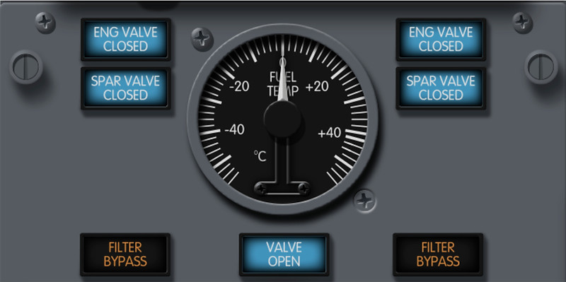
The Boeing 737 Fuel Control Panel is shown below it consist of switch for two booster pumps for each tank (number 1, center and number 2 tank) and each pump has its respective low pressure indication which is amber in colour, a cross feed valve and its indication which is blue in colour.
The fuel control panel also consist of amber colour filter bypass lights and a fuel temperature indicator.

BOEING 737 FUEL CONTROL PANEL
Fuel Quantity Indications
Fuel Quantity Indicator form an essential part of all aircraft fuel systems. These devices vary widely depending on the complexity of the fuel system and the aircraft on which they are installed.
There are two methods of measuring fuel quantity.
-
Measuring volume by varying a resistance by a float - normally restricted to light aircraft, is subject to manoeuvring error and cannot compensate for variations of density.
-
Measuring weight or mass by varying capacitance - essential on modern passenger aircraft - does not suffer from manoeuvring error and can compensate for variations of density.
Float Type Indicators
The float type indicators can be either
-
Mechanical Type
-
Electrical Type
The mechanical type consist of a float that follows the fuel level remains the primary sensing element, but a mechanical linkage is connected to move a pointer across the dial face of an instrument. This can be done with a crank and pinion arrangement that drives the pointer with gears, or with a magnetic coupling, to the pointer.
Electric fuel quantity indicators are more common than mechanical indicators in modern aircraft. Most of these units operate with direct current (DC) and use variable resistance in a circuit to drive a ratiometer-type indicator. The movement of a float in the tank moves a connecting arm to the wiper on a variable resistor in the tank unit.
This resistor is wired in series with one of the coils of the ratiometer-type fuel gauge in the instrument panel. Changes to the current flowing through the tank unit resistor change the current flowing through one of the coils in the indicator. This alters the magnetic field in which the indicating pointer pivots. The calibrated dial indicates the corresponding fuel quantity.

DC SUPPLY FUEL MEASURING SYSTEM
Capacitance Type
The capacitive method works by supplying the two plates of a capacitor with AC. The current that flows in the circuit now depends on four factors, the level of voltage applied, the frequency of the supply, the size of the plates and the dielectric constant of the material separating the plates. In our circuit three of these factors are fixed and the fourth, the dielectric constant, is variable because the dielectric consists of fuel and air. The higher the level of fuel in the tank the more fuel and less air will be in the capacitor probe, and vice versa.
The amount of current flowing in the circuit therefore depends on the amount of fuel/air between the plates and in measuring this current we can have an accurate indication of the mass of fuel in our tanks.
To compensate for change in aircraft attitude the capacitive system may have many capacitor probes in the tank connected in parallel to ‘average’ the measurement of the fuel in the tank. This enables the system to give an accurate indication irrespective of the aircraft attitude.
A commonly used type is the bridge circuit that measures the capacitance of the tank units uses a reference capacitor for comparison. When voltage is induced into the bridge, the capacitive reactance of the tank probes and the reference capacitor can be equal or different. The magnitude of the difference is translated into an indication of the fuel quantity in the tank calibrated in pounds.
The system can be made sensitive to the specific gravity (density) of the fuel so that although the volume of a quantity of fuel may increase with a temperature rise, the resulting decrease in the specific gravity will ensure that the indicated mass (weight) remains the same.

CAPACITANCE TYPE FUEL MEASURING SYSTEM
In addition to the fuel quantity gauges fitted to the fuel control panel and load control panel, most large aircraft are also provided with a means of physically checking the quantity of fuel in each tank, during maintenance. For the methods described below, the aircraft must be levelled both laterally and longitudinally to obtain accurate readings.
A ‘dip stick’ is a rod with a screwed fitting at the top, which screws into a mating fitting in the top skin of the tank. It protrudes into the tank and is calibrated to indicate the contents of the tank between certain limits. When unscrewed, the fuel level is indicated by the limit of fuel-wetting on the rod.
A ‘drip stick’ consists of a short outer tube, which is attached to an adaptor in the lower wing skin and protrudes upwards into the tank, and a long inner tube (calibrated in gallons or inches), which slides in the outer tube, and is secured to the adaptor by a bayonet fitting. The gap between the tubes is sealed against fuel leakage. To check fuel contents, the inner tube is unlocked and slowly withdrawn downwards; when the top of this tube falls below the fuel level, fuel will flow through it, and drain out of a hole in its base. The length of tube protruding from the adaptor, will indicate the tank contents. The volume of fuel, in gallons, may be obtained from tables provided in the aircraft Maintenance Manual.
A ‘magnetic level indicator’ is similar to a drip stick, but the top of the outer tube is sealed. A magnet mounted on a float which surrounds the outer tube rises and falls with the fuel level. A magnet is also mounted inside the top of the inner tube, and when this tube is unlocked, it may be carefully withdrawn downwards until the magnetic fields coincide. At this point the inner tube will be magnetically supported, and the contents will be indicated in the same way as with a drip stick.
Fuel Flow Indicator
A fuel flowmeter indicates an engine’s fuel use in real time. This can be useful to the pilot for ascertaining engine performance and for flight planning calculations. The types of fuel flow meter used on an aircraft depends primarily on the powerplant being used and the associated fuel system.
Measuring fuel flow accurately is complicated by the fact that the fuel mass changes with temperature or with the type of fuel used in turbine engines. In light aircraft with reciprocating engines, systems have been devised to measure fuel volume. The actual mass of fuel flowing to the engine is based on an assumption of the average weight of the fuel per unit volume.
With accurate fuel flow knowledge, numerous calculations can be performed to aid the pilot’s situational awareness and flight planning. Most high-performance aircraft have a fuel totalizer that electronically calculates and displays information, such as total fuel used, total fuel remaining onboard the aircraft, total range and flight time remaining at the present airspeed, rate of fuel consumption, etc.
On light aircraft, it is common to replace the original analog fuel indicators with electronic gauges containing similar capabilities and built-in logic. Some of these fuel computers, as they are called, integrate global positioning satellite (GPS) location information. Aircraft with fully digital cockpits process fuel flow data in computers and display a wide array of fuel flow related information on demand.
Relatively new types of fuel flow sensors/transmitters are available in new aircraft and for retrofit to older aircraft. One type of device found in home-built and experimental aircraft uses a turbine that rotates in the fuel flow. The higher the flow rate is, the faster the turbine rotates.
A Hall effect transducer is used to convert the speed of the turbine to an electrical signal to be used by an advanced fuel gauge similar to a fuel computer to produce a variety of calculated readouts and warnings. The turbine in this unit is in line with the fuel flow, but is fail safe to allow adequate fuel flow without interruption should the unit malfunction.
Another fuel flow sensor used primarily on light aircraft also detects the spinning velocity of a turbine in the fuel path. It too has a failsafe design should the turbine malfunction. In this unit, notches in the rotor interrupt an infrared light beam between an LED and phototransistor that creates a signal proportional to the amount fuel flow. This type of sensor may be coupled with an electronic indicator.
Increasing use of microprocessors and computers on aircraft enable the integration of fuel temperature and other compensating factors to produce highly accurate fuel flow information. Fuel flow sensing with digital output facilitates this with a high degree of reliability. Thermal dispersion technology provides flow sensing with no moving parts and digital output signals. The sensor consists of two resistance temperature detectors (RTDs). One is a reference RTD that measures the temperature of the fuel. The other is the active RTD. It is heated by an adjacent element to a temperature higher than the fuel. As the fuel flows, the active element cools proportionally to the fuel flow. The temperature difference between the two RTDs is highest at no flow.
The RTDs are connected to an electronic assembly that supplies power to the heater and uses sensing circuitry and a microprocessor to control a constant temperature difference between the heated and unheated RTDs. The electrical current to the heater is proportional to the mass flow of the fuel. As mentioned, the reference RTD is used as a temperature sensor to provide a temperature output and allow for temperature compensation of the flow measurement.

FUEL FLOW INDICATOR WORKING
Fuel Temperature Gauge
Water may enter in the fuel system during refueling, or as a result of condensation in the tanks, and, when the fuel temperature falls below 0 deg. C, the suspended water droplets may freeze. These frozen droplets collect at the low pressure filters, and may restrict or block fuel flow to the engines. To prevent this, a filter by-pass and blockage indicator may be fitted, or a de-icing additive such as methyl alcohol may be used in the fuel. However, in most large aircraft provision is made for heating the fuel before it enters the filters.
Fuel heaters are usually heat-exchangers, and may utilize engine oil, or air tapped from the engine compressors, as the heating medium. On some aircraft the engine oil coolers, which are in continuous use, are oil/fuel heat exchangers, and serve the additional purpose of heating the fuel. A heat exchanger operated by hot compressor air may be used in addition to the oil cooler, or may be used by itself for the purpose of heating the fuel. Oil/fuel heat exchangers are automatic in operation, oil flow being thermostatically controlled, but air/fuel heat exchangers may be either manually or automatically controlled.
A manually controlled fuel heating system usually consists of a pressure differential switch on the fuel filter, which operates a warning lamp in the crew compartment, and an electrically-operated valve on the heat exchanger, which is controlled by a switch adjacent to the warning lamp; a second warning lamp may also be included, to signify that the heating valve is open. When fuel flow through the filter becomes restricted by ice, the differential pressure across the filter increases, until it is sufficient to operate the icing warning lamp. The heat-exchanger valve should then be opened to admit hot compressor air to the heat-exchanger and to warm the fuel. Fuel temperature on the outlet side of the filter is indicated by an instrument on the fuel control panel. With this type of system, the period and frequency of operation of the heat exchanger may be limited.
An automatically controlled fuel heating system consists of a thermostatically controlled air inlet valve on the heat exchanger, which progressively opens and closes to maintain fuel outlet temperature within pre-set limits above 0 deg. C.
Actual fuel temperature is indicated on an instrument on the fuel control panel, but no action is required by the crew.
As previously mentioned, monitoring fuel temperature can inform the pilot when fuel temperature approaches that which could cause ice to form in the fuel system, especially at the fuel filter. Many large and high-performance turbine aircraft use a resistance type electric fuel temperature sender in a main fuel tank for this purpose. It can display on a traditional ratiometer gauge or can be input into a computer for processing and digital display.
A low fuel temperature can be corrected with the use of a fuel heater if the aircraft is so equipped. Also as mentioned, fuel temperature can be integrated into fuel flow processing calculations. Viscosity differences at varying fuel temperatures that affect fuel flow sensing accuracy can be corrected via microprocessors and computers.
FUEL TEMPERATURE GAUGE
Fuel Pressure Gauge
Monitoring fuel pressure can give the pilot early warning of a fuel system related malfunction. Verification that the fuel system is delivering fuel to the fuel metering device can be critical. Simple light reciprocating-engine aircraft typically utilize a direct reading Bourdon tube pressure gauge. It is connected into the fuel inlet of the fuel metering device with a line extending to the back of the gauge in the cockpit instrument panel.
A more complex aircraft may have a sensor with a transducer located at the fuel inlet to the metering device that sends electrical signals to a cockpit gauge. In aircraft equipped with an auxiliary pump for starting and to backup the engine-driven pump, the fuel pressure gauge indicates the auxiliary pump pressure until the engine is started. When the auxiliary pump is switched off, the gauge indicates the pressure developed by the engine driven pump.
