
Fire and Overheat Detection System
Introduction
To detect fires or overheat conditions, in an aircraft detectors are placed in the various zones which needs to be monitored. Fire protection systems do not rely on observation by crew members as a primary method of fire detection.
An ideal fire detector system includes as many of the following features as possible:
-
No false warnings under any flight or ground condition.
-
Rapid indication of a fire and accurate location of the fire.
-
Accurate indication that a fire is out.
-
Indication that a fire has re-ignited.
-
Continuous indication for duration of a fire.
-
Means for electrically testing the detector system from the aircraft cockpit.
-
Resists damage from exposure to oil, water, vibration, extreme temperatures, or handling.
-
Light in weight and easily adaptable to any mounting position.
-
Circuitry that operates directly from the aircraft power system without inverters.
-
Minimum electrical current requirements when not indicating a fire.
-
Cockpit light that illuminates, indicating the location of the fire, and with an audible alarm system.
-
A separate detector system for each engine.
The types of detectors most commonly used for fast detection of fires are the rate-of-rise, optical sensor, pneumatic loop, and electric resistance systems.
In smaller Aircrafts fires detectors commonly used are:
-
Overheat detectors
-
Rate-of-temperature-rise detectors
-
Flame detectors
-
Observation by crewmembers
In larger aircraft combination of the following methods are used :
-
Rate-of-temperature-rise detectors
-
Radiation sensing detectors
-
Smoke detectors
-
Overheat detectors
-
Carbon monoxide detectors
-
Combustible mixture detectors
-
Optical detectors
-
Observation by crew or passengers
Classes of Fires
The following classes of fires that are likely to occur onboard aircraft:
Class A
The fires involving ordinary combustible materials, such as wood, cloth, paper, rubber, and plastics.
Class B
The fires involving flammable liquids, petroleum oils, greases, tars, oil-based paints, lacquers, solvents, alcohols, and flammable gases.
Class C
The fires involving energized electrical equipment in which the use of an extinguishing media that is electrically non conductive is important.
Class D
The fires involving combustible metals, such as magnesium, titanium, zirconium, sodium, lithium, and potassium.

TYPES OF FIRES IN AN AIRCRAFT
Fire Zones
Power plant compartments are classified into zones based on the airflow through them.
Class A zone
The area of heavy airflow past regular arrangements of similarly shaped obstructions. The power section of a reciprocating engine is usually of this type.
Class B zone
The area of heavy airflow past aerodynamically clean obstructions. Included in this type are heat exchanger ducts, exhaust manifold shrouds, and areas where the inside of the enclosing cowling or other closure is smooth, free of pockets, and adequately drained so leaking flammables cannot puddle. Turbine engine compartments may be considered in this class if engine surfaces are aerodynamically clean and all airframe structural formers are covered by a fireproof liner to produce an aerodynamically clean enclosure surface.
Class C zone
The area of relatively low airflow. An engine accessory compartment separated from the power section is an example of this type of zone.
Class D zone
The area of very little or no airflow. These include wing compartments and wheel wells where little ventilation is provided.
Class X zone
The area of heavy airflow and of unusual construction, making uniform distribution of the extinguishing agent very difficult. Areas containing deeply recessed spaces and pockets between large structural formers are of this type. Tests indicate agent requirements to be double those for Class A zones.
Types of Detector Systems
Three detector system types in common use are
-
Thermal Switch
-
Thermocouple
-
Continuous Loop.
Thermal Switch System
These detectors are normally situated at points most likely to be affected by fire,such as an engine breather outlet or hot air ducting. The type most commonly used is a switch, the contacts of which are actuated by the differential expansion of dissimilar metals. The thermal switch is a unit type and called a spot or point detector.

THERMAL SWITCH DETECTOR
A thermal switch fire detection system is a circuit in which one or more thermal switches are connected in an electrical circuit which also has a warning light and an aural alarm to warn the flight crew that an overheat condition exists in a particular area. If more than one thermal switch is in the circuit, the switches are connected in parallel. This makes sure that if any one switch closes a warning is given.

SINGLE LOOP THERMAL SWITCH FIRE DETECTION SYSTEM
In some circuits the detectors are connected between two wiring loops, either of which may be supplied through a magnetic circuit breaker. A short circuit in the energized loop results in operation of the magnetic circuit breaker and the supply is then routed to the second loop. This prevents a false indication of fire. The system can withstand one fault, either an electrical open circuit or a short to ground without sounding a false alarm. A double fault must exist before a false fire warning can occur.
Provision is made in the control unit to output a fault signal which activates a fault indicator whenever the short discriminator circuit detects a short in the sensing element loop. This is a requirement for transport category aircraft because such a short disables the fire detection system.

DOUBLE LOOP THERMAL SWITCH FIRE DETECTION SYSTEM
Thermocouple System
A Thermocouple is the junction of two dissimilar metals which generates a small electric current that varies according to the temperature of the junction. For this reason it does not require an external power source. A thermocouple gives the rate of temperature rise.
The dissimilar metals can be constantan and iron, Alumel and Chromel, or some other combination of metals or alloys which will produce the required results. The complete thermocouple circuit consists of the ‘cold’ junction, the ‘hot’ junction, electric leads (made from the same material as the thermocouple).
The point at which these metals are joined and exposed to the heat of a fire is called a hot junction.
If the temperature rises rapidly, the thermocouple produces a voltage because of the temperature difference between the reference junction and the hot junction. If both junctions are heated at the same rate, no voltage results.

BASIC THERMOCOUPLE PRINCIPLE
The system consists of a relay box, warning lights, and thermocouples. The wiring system of these units may be divided into the following circuits:
-
Detector circuit
-
Alarm circuit
-
Test circuit
The relay box contains two relays, the sensitive relay and the slave relay, and the thermal test unit.
Such a box may contain from one to eight identical circuits, depending on the number of potential fire zones. The relays control the warning lights. In turn, the thermocouples control the operation of the relays. The circuit consists of several thermocouples in series with each other and with the sensitive relay.
In the engine compartment, there is a normal, gradual rise in temperature from engine operation; because it is gradual, both junctions heat at the same rate and no warning signal is given.
If there is a fire, the measuring junction (hot junction) heats more rapidly than the reference junction (cold junction) & voltage produced causes a current to flow within the detector circuit. Any time the current is greater than 4 milliamperes (0.004 ampere), the sensitive relay closes. This completes a circuit from the aircraft power system to the coil of the slave relay. The slave relay then closes and completes the circuit to the warning light to give a visual fire warning.
The total number of thermocouples used in individual detector circuits depends on the size of the fire zones and the total circuit resistance, which usually does not exceed 5 ohms.
When the sensitive relay opens, the circuit to the slave relay is interrupted and the magnetic field around its coil collapses. The coil then gets a voltage through self-induction but, with the resistor across the coil terminals, there is a path for any current flow as a result of this voltage, eliminating arcing at the sensitive relay contacts.
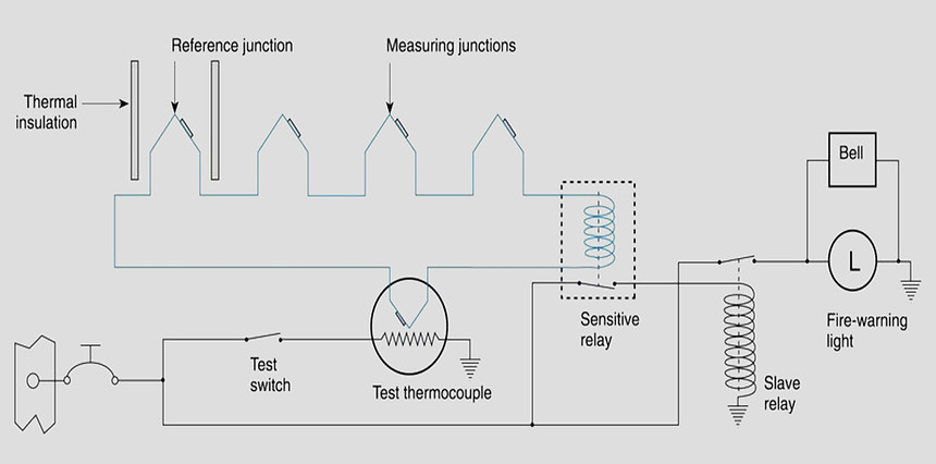
THERMOCOUPLE FIRE DETECTION SYSTEM
Continuous-Loop Systems
Transport aircraft almost exclusively use continuous thermal sensing elements for powerplant and wheel well protection. These systems offer superior detection performance and coverage, and they have the proven ruggedness to survive in the harsh environment of modern turbofan engines.
A continuous-loop detector or sensing system permits more complete coverage of a fire hazard area than any of the spot-type temperature detectors.
Two widely used types of continuous-loop systems are
-
Thermistor Type Detectors
-
Pneumatic Pressure Detector
Thermistor Type Continuous Loop System
The Thermistor type continuous loop system consist of
-
Fenwal System
-
Kidde System
Fenwal System
The Fenwal system uses a slender Inconel tube packed with thermally sensitive eutectic salt and a nickel wire center conductor.

FENWAL PROBE
Lengths of these sensing elements are connected in series to a control unit. The elements may be of equal or varying length and of the same or different temperature settings. The control unit, operating directly from the power source, impresses a small voltage on the sensing elements. When an overheat condition occurs at any point along the element length, the resistance of the eutectic salt within the sensing element drops sharply, causing current to flow between the outer sheath and the center conductor.
This current flow is sensed by the control unit, which produces a signal to actuate the output relay and activate the alarms. When the fire has been extinguished or the critical temperature lowered below the set point, the Fenwal system automatically returns to standby alert, ready to detect any subsequent fire or overheat condition. The Fenwal system may be wired to employ a loop circuit.
In this case, should an open circuit occur, the system still signals fire or overheat.
If multiple open circuits occur, only that section between breaks becomes inoperative.

FENWAL FIRE DETECTION SYSTEM
Kidde System
In the Kidde continuous-loop system, two wires are imbedded in an inconel tube filled with a thermistor core material.
Two electrical conductors go through the length of the core. One conductor has a ground connection to the tube, and the other conductor connects to the fire detection control unit.
As the temperature of the core increases, electrical resistance to the ground decreases. The fire detection control unit monitors this resistance. If the resistance decreases to the overheat set point, an overheat indication occurs in the flight deck. Typically, a 10-second time delay is incorporated for the overheat indication. If the resistance decreases more to the fire set point, a fire warning occurs.
When the fire or overheat condition is gone, the resistance of the core material increases to the reset point and the flight deck indications disappear. The rate of change of resistance identifies an electrical short or a fire. The resistance decreases more quickly with an electrical short than with a fire.
In some aircraft, in addition to fire and overheat detection, the Kidde continuous-loop system can supply nacelle temperature data to the airplane condition monitoring function of the aircraft in-flight monitoring system (AIMS).

KIDDE SYSTEM
The resistance of a sensor varies inversely as it is heated; as sensor temperature is increased, its resistance decreases. Each sensor is composed of two wires embedded in thermistor material that is encased in a heavy wall inconel tube for high strength at elevated temperatures. The electrical connectors at each end of the sensor are ceramic insulated. The inconel tubes are shrouded in a perforated stainless-steel tube and supported by Teflon-impregnated asbestos bushings at intervals. The shroud protects the sensor from breakage dueto vibration, abrasion against airplane structure, and damage from maintenance activity.
The resistance of a sensor also varies inversely with its length, the increments of length being resistances in parallel. The heating of a short length of sensor out of a given length requires that the short length be heated above the temperature alarm point, so the total resistance of the sensor decreases to the alarm point. This characteristic permits integration of all temperatures throughout the length of the installation rather than sensing only the highest local temperature. The two wires encased within the thermistic material of each inconel tube form a variable resistance network between themselves, between the detector wire and the inconel tube, and between each adjacent incremental length of sensor. These variable resistance networks are monitored by the application of 28 volts direct current (DC) to the detector wire from the detector control unit.
System Test
The integrity of the continuous-loop fire detection system may be tested by actuating a test switch in the flight deck that switches one end of the sensing element loop from its control circuit to a test circuit built into the control unit, which simulates the sensing element resistance change due to fire.
If the sensing element loop is unbroken, the resistance detected by the control circuit is that of the simulated fire, and the alarm is activated. The test demonstrates, in addition to the continuity of the sensing element loop, the integrity of the alarm indicator circuit and the proper functioning of the control circuits.
The thermistic properties of the sensing element remain unchanged for the life of the element (no irreversible changes take place when heated); the element functions properly as long as it is electrically connected to the control unit.

CONTINUOUS LOOP FIRE DETECTION SYSTEM TEST
Dual-Loop Systems
Dual-loop systems are two complete basic fire detection systems with their output signals connected so that both must signal to result in a fire warning. This arrangement, called AND logic, results in greatly increased reliability against false fire warnings from any cause. Should one of the two loops be found inoperative at the preflight integrity test, a cockpit selector switch disconnects that loop and allows the signal from the other loop alone to activate the fire warning.
Since the single operative loop meets all fire detector requirements, the aircraft can be safely dispatched and maintenance deferred to a more convenient time. However, should one of the two loops become inoperative in flight and a fire subsequently occur, the fire signaling loop activates a cockpit fault signal that alerts the flight crew to select single-loop operation to confirm the possible occurrence of fire.
Dual-loop systems automatically perform the loop switching and decision-making function required of the flight crew upon appearance of the fault indication in the cockpit, a function called automatic self-interrogation. Automatic self interrogation eliminates the fault indication and assures the immediate appearance of the fire indication should fire occur while at least one loop of the dual-loop system is operative. Should the control circuit from a single-loop signal fire, the self-interrogation circuit automatically tests the functioning of the other loop. If it tests operative, the circuit suppresses the fire signal because the operative loop would have signaled if a fire existed. If, however, the other loop tests inoperative, the circuit outputs a fire signal. The interrogation and decision takes place in milliseconds, so that no delay occurs if a fire actually exists.
Fire Detection Control Unit (Fire Detection Card)
The control unit for the simplest type of system typically contains the necessary electronic resistance monitoring and alarm output circuits housed in a hermetically sealed aluminum case fitted with a mounting bracket and electrical connector. For more sophisticated systems, control modules are employed that contain removable control cards with circuitry for individual hazard areas and/or unique functions. In the most advanced applications, the detection system circuitry controls all aircraft fire protection functions, including fire detection and extinguishing for engines, APUs, cargo bays, and bleed-air systems
Pneumatic Continuous-Loop Systems
Some smaller turboprop aircraft are outfitted with pneumatic single point detectors. The design of these detectors is based on the principles of gas laws.
Pneumatic fire detectors are constructed from a thin (typically 2mm diameter) sensor tube filled with helium, and a gas-charged metal-hydride centre core. The tube is sealed at one end and attached to a pressure-sensing device (the responder) at the other end. The responder assembly is electrically isolated from the sensing tube and contains two pressure switches, a resistor and electrical connector.
The normally open (NO) alarm switch is closed when a fire or overheat causes the helium to expand. A normally closed (NC) integrity switch in the responder is held closed by the helium pressure; the internal resistor and switch contacts form the warning circuit. Measurement of the resistor value by an external circuit provides an indication of fire, over- heat or loss of integrity.
In the non-alarm condition, a monitoring circuit detects the known resistor value. When large sections of the sensor tube are heated, the increased pressure of the helium causes the alarm switch to close; this bypasses the resistor and the monitoring circuit signals an alarm condition. When the overheat condition is removed, the gas pressure decreases and the switch opens.
This type of sensor is designed as a single-sensor detection system and does not require a control unit.

BASIC PNEUMATIC CONTINUOUS DETECTION PROBE

BASIC PNEUMATIC FIRE DETECTION SYSTEM
The pneumatic continuous-loop systems are also known by their manufacturers’ names Lindberg, Systron-Donner, and Meggitt Safety Systems. They are typically used in a dual-loop design to increase reliability of the system.

A TYPICAL SYSTRON-DONNER ELEMENT
The pneumatic detector has two sensing functions. It responds to an overall average temperature threshold and to a localized discrete temperature increase caused by impinging flame or hot gasses. Both the average and discrete temperature are factory set and are not field adjustable.
The fire/overheat detector serves as a fixed-volume device filled with helium gas. The helium gas pressure inside the detector increases in proportion to the absolute temperature and operates a pressure diaphragm that closes an electrical contact, actuating the alarm circuit. The pressure diaphragm within the responder assembly serves as one side of the electrical alarm contact and is the only moving part in the detector. The alarm switch is preset at an average temperature.
Typical temperature ranges for average temperature settings are 200 °F (93 °C) to 850 °F (454 °C).
The fire/overheat detector’s sensor tube also contains a hydrogen-filled core material.
Large quantities of hydrogen gas are released from the detector core whenever a small section of the tube is heated to the preset discrete temperature or higher. The core outgassing increases the pressure inside the detector and actuates the alarm switch. Both the averaging and discrete functions are reversible.
When the sensor tube is cooled, the average gas pressure is lowered, and the discrete hydrogen gas returns to the core material. The reduction of internal pressure allows the alarm switch to return to its normal position, opening the electrical alarm circuit.
Combination Fire and Overheat Warning
The analog signal from the thermistor-sensing element permits the control circuits to be arranged to give a two level response from the same sensing element loop.
The first is an overheat warning at a temperature level below the fire warning indicating a general engine compartment temperature rise, such as would be caused by leakage of hot bleed air or combustion gas into the engine compartment. It could also be an early warning of fire and would alert the crew to appropriate action to reduce the engine compartment temperature.
The second-level response is at a level above that attainable by a leaking hot gas and is the fire warning