
Engine and Fuel Instruments
Introduction
At the present time there are three principal types of engine in use, namely, piston (unsupercharged and turbocharged), turbo propeller, and pure turbine, and their selection as the means of propulsion for any one type of aircraft depends on its size and operational category.
In each case there are certain parameters that are required to be monitored to ensure that they are operated in accordance with their designed performance ratings, and within specific limitations. For example r.m.p. , fuel flow, oil pressure, engine pressure, exhaust gas temperature, fuel pressure etc.
Monitoring is accomplished by means of specifically designed instrument systems, the sensor units of which may, in very basic form, be incorporated within an indicator, or be of the remote type which transmit data in the form of electrical signals to 'clock'-type indicators, or to electronic display units.
Pressure gauge
The method of pressure measurement depends largely upon the value of the pressure to be measured and how it is to be displayed. Not surprisingly, high pressures such as those found in a hydraulic system, for example, require more robust methods than the low pressures associated with piston engine manifolds.
In early aircraft it was normal to connect the pressure instrument (gauge) on the pilot's instrument panel direct to the pressure source, in which case the pressure measuring device is contained within the instrument itself. Thus, for example, engine oil pressure is piped to a flexible element within the pressure gauge and this is known as a direct-reading instrument.
The disadvantages of such a system are that a leak in the connecting pipe not only renders the pressure gauge useless, but also presents a loss of vital engine lubricant and a potential fire hazard. Furthermore, the weight of piping required to convey high pressure fluids is not inconsiderable.
To overcome these disadvantages it has become the usual practice in all but the simplest cases to use remote reading instruments, in which the pressure is measured at source and transmitted to the pilot's instruments by mechanical or electrical means.
A simple mechanical transmitter, now rarely used, consisted of a cylinder containing a free piston. One side of the piston was connected to the pressure source, say hydraulic system pressure, and the other was connected to the instrument panel pressure gauge by an enclosed pipe filled with non-flammable fluid.
The force exerted on the piston by the hydraulic system pressure was transmitted by the enclosed system to the pressure gauge. Such methods have been replaced almost entirely by electrical transmission of a signal proportional to the pressure exerted on a transducer, the signal then operating a suitably calibrated indicator in the cockpit.
Direct-reading pressure gauges
Where relatively high pressures are involved, such as engine oil pressure or hydraulic systems, the type of pressure measuring element commonly used in direct-reading pressure gauges is the Bourdon tube.
The device comprises a flattened tube formed into a semi-circle and closed at one end. The other end of the tube is connected to the pressure source. The tube is made of a flexible material so that, when pressure is applied to the inside of it, it tends to straighten.
This tendency is opposed by a spring, or by the natural resistance of the tube itself, so the extent of the 'straightening' movement is proportional to the pressure applied. The closed end of the tube is connected through gearing to the instrument pointer, which moves against a calibrated scale to indicate system pressure in the chosen units of measurement.

BOURDON TUBE
Where lower pressures are to be measured the Bourdon tube is not sufficiently sensitive. The pressure measuring elements used are typically corrugated capsules.
Figure illustrates an example of the use of these elements in a piston engine manifold pressure gauge. Manifold air pressure (MAP) typically ranges from a value less than ambient atmospheric pressure to a small amount (perhaps 1 or 2 bar) above, and so it must be measured against absolute zero (i.e. the pressure in a total vacuum).
To achieve this, two sensing capsules are used, one of which is evacuated and spring loaded to respond to ambient atmospheric pressure and the other of which is con- nected internally to the engine manifold by piping. The two capsules are linked mechanically to the instrument pointer.

MANIFOLD AIR PRESSURE GAUGE OPERATING PRINCIPLE
The manifold air pressure or boost gauge is usually calibrated to read absolute pressure in inches of mercury (in Hg), thus at sea level with the engine stopped it will indicate approximately 30 in Hg.
When the engine is running and the pistons are drawing air into the cylinders through the intake manifold, a partial vacuum is created in the manifold and the gauge will read less than ambient atmospheric pressure. If the engine is supercharged, or `boosted', the supercharger or turbocharger will force air into the manifold at higher engine powers and the manifold pressure will be greater than ambient atmospheric pressure. The MAP is a measure of the power being developed by a piston engine, hence the reason for indicating it to the pilot.
In the system illustrated in Figure, the situation depicted is that which would exist at sea level with the engine stopped. Ambient atmospheric pressure is acting on the outside of the aneroid capsule, against the force of its internal spring, and on the inside and outside of the manifold capsule. The forces exerted are in balance and the gauge pointer is indicating 30 in Hg against the calibrated scale.
If the engine were to be started and run at low rpm, the pistons would draw a partial vacuum in the intake manifold and the force exerted by the manifold capsule would decrease. This is because the ambient atmospheric pressure acting on the outside of the manifold capsule tends to compress the capsule and this is transmitted to the gauge pointer through mechanical linkage and gearing. The amount of compression is restricted by the atmospheric pressure acting on the outside of the sealed, aneroid capsule and so the pointer movement is proportional to the change in manifold air pressure.
At increased engine rpm and power the supercharger-boosted pressure in the manifold becomes greater than atmospheric pressure and the manifold capsule expands, moving the gauge pointer toward a higher value. The extent of movement is limited by the opposing force of the spring sur- rounding the aneroid capsule.
Remote-Reading Pressure Gauges
The use of direct-reading pressure gauges is mainly restricted to small aircraft with a limited number of gauging requirements. The more complex the aircraft and its systems, the greater the number of pressure measurements required and the less practical it becomes to pipe these to an instrument array in the cockpit. Consequently, the various pressures are measured at source and transmitted electrically to the pilot's instrument displays, which may comprise individual electrically operated indicators or a computerised electronic display.
The conversion of pressure into a proportional electrical signal and its transmission to a calibrated indicating instrument necessarily involves the conversion of mechanical movement into an electrical output at the measuring source and, in the case of a mechanical indicator on the flight deck, a reversal of this conversion.
There are various types of device for achieving this, including the synchronous transmission, or synchro, system, the inductive transmitter and the potentiometer system.
Synchronous transmission
In the example, oil pressure is sensed in a capsule that expands against a spring to create linear movement proportional to the measured pressure.
This movement is transmitted mechanically to a rotor upon which is wound a coil carrying alternating current. The rotor is positioned centrally within a stator having three coils at 120º spacing. The electromagnetic field created around the rotor induces a current flow in each of the stator coils, the strength of the current in each coil being dependent upon the orientation of the rotor.
These three transmitter currents are fed to, and repeated in, an identical receiver stator system located behind the cockpit instrument panel, where they create a magnetic field identical to that in the transmitter. This field interacts with the a.c. induced field surrounding the receiver rotor coil, causing the receiver rotor to rotate and adopt an orientation corresponding to that of the transmitter rotor. The receiver rotor is mechanically connected to the pointer of a pressure-indicating instrument.

Synchronous transmission system
Induction transmitter
In this type of pressure transmission system the pressure to be measured is led to a capsule inside the pressure transmitter, which is located as close as possible to the pressure source. The capsule is mechanically connected to a permanent magnet armature, and linear expansion or contraction of the capsule moves the armature linearly against the opposition of a spring.
The armature is surrounded by two sets of coils, supplied with current and connected to a moving coil indicator on the flight deck. As the armature moves, its position relative to each of the coils differs, and the inductance of the two coils will vary in direct proportion to the pressure being measured. This will cause the output current from the coils to vary, positioning the pointer of the moving coil indicator pressure gauge accordingly.

Induction transmitter and ratiometer
The type of moving coil indicator typically associated with this type of remote reading pressure gauge is the ratiometer. Current from the transmitter coils is supplied to two coils wound around armatures on a spindle-mounted iron core. The core is positioned eccentrically between the poles of a permanent magnet, so that the air gap between the core and the magnet poles is greater on one side than on the other.
Where the gap is greatest, the strength of the permanent magnetic field will be weakest and vice versa. Current flowing through the core coils creates electro-magnetic fields that will interact with the perma- nent magnetic field. If the two current flows are equal, their magnetic field strengths will be equal and of opposite polarity, thus cancelling each other and the iron core will be held stationary.
If, however, the current flow in coil B is greater than that in coil A the stronger magnetic field surrounding coil B will be attracted toward the larger air gap where the field strength is weaker, rotating the iron core on its spindle and moving the attached gauge pointer against a calibrated scale. At the same time, the weaker induced field sur- rounding coil A is moved into a narrowing air gap where the permanent magnetic field is stronger.
This will eventually arrest the rotation of the core when the opposition of the permanent field matches the attraction of the induced field and the gauge pointer will indicate the changed pressure that caused the current imbalance. If the current flow in coil A is greater than that in coil B, the effect will be the reverse of that described above.
Potentiometer transmission
This type of pressure transmission system uses an inductance transmitter similar or identical to that described above, but its output current is amplified and used to drive an a.c. motor, which is connected to the pointer of the pressure gauge and a potentiometer. In simplistic terms, the potentiometer is a variable resistance connected to an a.c. supply, the output of which is fed back to the transmitter amplifier.
As the motor drives the gauge pointer, the potentiometer resistance varies until its output current and phase balances the transmitter signal and supply to the motor ceases, holding the gauge pointer at its new position.
Piezo-electric transmitters
In most large modern aircraft the transmission of low pressure utilises solid- state transmitters that operate on the piezoelectric principle. These comprise a thin stack of quartz discs impregnated with metallic deposits. When acted upon by pressure the disc stack flexes and small electrical charges are produced.
The polarity of the induced charge depends upon the direction of flexing, due to increased or decreased pressure, and the output is amplified and used to actuate an electronic representation of a pressure indicator.
Pressure gauge indications
Aircraft pressure gauges use a central pointer moving against a circular calibrated scale. The gauge scale is calibrated in the chosen units of pressure measurement and coloured markings are added in many cases to indicate operating limits and ranges.
In the case of the engine oil pressure gauge illustrated, maximum and minimum oil pressures are indicated by radial red lines and the normal operating range of pressures by a green arc. If these markings are made on the glass cover, rather than the instrument face, it is required that a white radial line, known as a slip indicator, must be painted on the glass and the adjoining casing to indicate movement of the glass relative to the casing.
Piston engine manifold air pressure (MAP) gauges are also usually colour coded to indicate operating power ranges and limits. A red radial line indicates the maximum permissible MAP for take-off power and blue and green arcs indicate the lean and rich mixture ranges, respectively.
Normally aspirated (unsupercharged) piston engines with fuel injection systems often have a fuel pressure gauge with coloured arcs to indicate lean and rich mixture ranges, since in these power plants fuel pressure is directly proportional to engine power. In the cruise at reduced power a lean mixture may be used for fuel economy, but at high power settings it is essential to use a rich mixture to avoid detonation and engine damage. The coloured arcs are the same as those on a MAP gauge.
Pressure operated switches
In many cases the pilot does not need to know the actual operating pressure of a particular system, but merely that it is within acceptable limits.
Examples of this are the constant speed drive unit (CSDU) oil pressure, where only a low pressure warning is necessary, and similarly the hydraulic system pressure in some light aircraft with very limited hydraulically operated devices. In these cases it is usual to use a simple transmitter in the form of a pressure-operated switch connected to a warning light in the cockpit.
The source pressure is applied to a small piston in the switch assembly, the movement of which is opposed by a calibrated spring. When the source pressure is within operating limits the spring is compressed and a switch connected to the piston is held with its contacts open. If pressure falls below a preset value, the spring overcomes the pressure acting on the piston and moves the switch to close the contacts and connect supply current to the warning light.
Clearly, the same principle, but with suitably amended calibration, can be adapted to indicate excessive pressure. An example of this is the oil filter bypass warning light, which will be activated as the filter becomes clogged and the pressure differential across it increases, to warn the pilot that the filter bypass valve will open unless the filter is changed at the earliest opportunity.
Temperature gauge
Temperature gauges are used in aircraft piston engines to monitor lubricating oil temperature and cylinder head temperature (CHT). Additionally, carburettor air intake temperature is measured in some engines, to give warning of carburettor icing, and exhaust gas temperature may also be monitored, since this gives an indication of combustion efficiency and is useful when adjusting mixture settings.
In aircraft turbine engines lubricating oil temperature and exhaust gas temperature (EGT) are invariably monitored. In the case of turbo-propeller engines, turbine inlet gas temperature may be measured instead of EGT.
There are fundamentally two methods of temperature sensing in common use in aircraft engines and systems:
-
Variable Resistance Method
-
Thermocouple.
The variable resistance type of sensing element makes use of the tendency of metals to change their conductivity as temperature changes, such that the conductivity decreases (i.e. resistance increases) with increasing temperature. The thermocouple operates on the principle that heat energy can be converted into electrical energy due to what is known as the Seebeck effect.
The type of sensor used depends mainly upon the degree of heat involved. The sensing elements that make use of resistive change with temperature are not generally suitable for use with the high temperatures associated with exhaust gas, but are ideal for the temperature ranges experienced in engine lubricating oil systems. The electrical energy gener- ated by the Seebeck effect is small, so this type of sensor is better suited for measurement of high temperatures.
Resistive systems
A resistive temperature sensing system comprises a sensing element containing a resistance element supplied with low voltage electrical current and connected in series with an indicator that will convert the electrical output of the sensor into mechanical movement of an instrument pointer.
The electrical supply is usually d.c., but in some cases single phase a.c. may be used. The sensor element is contained within a closed tube, or `bulb', which is immersed in the fluid to be measured. As fluid temperature increases, the resistance of the element will increase and current flow to the indicator unit will decrease in proportion.
Sensing unit
The d.c. supply is led to the sensing probe through a two-pin connector. The resistive element is wound around a central core made of non-conducting material and enclosed within a leak proof casing made of thin, heat- conducting material, typically copper or aluminium. The tube is inserted into the fluid system (e.g. the engine lubricating oil system) and held in place by a threaded union nut.
The calibrating coil has a resistance value that is set during manufacture to determine the temperature/resistance characteristic of the sensing probe for the temperature range it is intended to measure.

RESISTIVE TEMPERATURE SENSING UNIT
Indicating unit
The temperature gauge associated with resistive temperature measurement is typically a moving coil instrument, which may be operated by a Wheatstone bridge circuit.
The Wheatstone bridge comprises two pairs of series resistances, connected in parallel. The resistances are connected to a low voltage circuit, typically 24 V d.c. In the diagram above, resistances R1, R2 and R3 are of identical value, whilst resistance R4 is the element of the temperature probe and varies with the temperature of the sensed fluid.
Resistances R1 and R2 are connected in series and form one side of the bridge system, whilst resistances R3 and R4 are also connected in series and form the other side. A coil surrounding an iron core is connected from point A, between resistances R1 and R2, to point B between resistances R3 and R4.

TEMPERATURE PROBE AND WHEATSTONE BRIDGE CIRCUIT
Let us assume for the moment that the temperature of the sensed fluid is such that the resistance value of R4 is the same as the other three resistances. Since the total resistance on each side of the parallel bridge circuit is the same, it follows that the current flow will also be the same on each side. Bearing Ohm's Law in mind, it therefore follows that the voltage at points A and B will be identical and there will consequently be no current flow through the armature coil, since current will only flow from a higher voltage point to a lower one.
Suppose now the temperature of the sensed fluid increases. The resistance of the probe element will increase and current flow through resistance R4 will decrease (Ohm's Law again, I = V/R), whilst the current flow through resistance R2 remains constant. As a result, the voltage at point B will increase (V = IR), whilst the voltage at point A remains constant; the voltage difference will cause a current flow from B to A and this current flow will induce a magnetic field about the coil, concentrated in the soft iron armature. The armature is situated within a permanent magnetic field, and magnetic attraction/repulsion will cause the armature to rotate upon its spindle. The direction of rotation will depend upon the polarity of the armature field, which is in turn dependent upon the direction of current flow in the armature coil. The armature is connected mechanically to the pointer of the temperature gauge.
If the temperature of the sensed fluid were to decrease, the resistance of the probe element would decrease and current flow through resistance R4 would increase above that through resistance R2. The voltage at point A would now be greater than that at point B and current flow through the armature coil would be from A to B, reversing the polarity of the induced magnetic field. The armature would consequently rotate in the opposite direction, indicating the reduced temperature on the gauge.
Thermocouple sensors
Thermocouple temperature measuring sensors require no external electrical supply, since they directly convert heat energy into electrical energy.
They operate on the principle that, if two conductors made of dissimilar metals are connected at either end, a potential difference will exist between the two junctions provided that there is a temperature difference between the junctions. The value of the potential difference will be directly proportional to the temperature difference and, since the two joined conductors form a loop, will cause current to flow around the loop.
Clearly, the greater the temperature/potential difference the greater the current flow and, when suitably amplified, the thermocouple current can be made to operate the indicator of a temperature gauge.

THERMOCOUPLE PRINCIPLE
For the measurement of piston engine cylinder head temperature, where the temperature range is typically of the order of 400ºC to 850ºC, the metals used are usually copper and copper±nickel alloy, or iron and copper±nickel alloy for the higher end of the range.
For gas turbine exhaust gas temperature measurement, where the maximum temperature may be as high as 1100ºC, nickel±aluminium and nickel±chromium alloy conductors are usually used.
Cylinder head temperature thermocouples typically take the form of a `washer' bolted to the cylinder head and forming the hot junction of the thermocouple. The cold junction is at the amplifier of the temperature indicator. This is known as a surface contact sensor.

SURFACE CONTACT SENSOR
The measurement of gas temperature uses an immersion sensor which, as its name suggests, consists of a probe immersed in the hot gas flow, containing the hot junction of the thermocouple. The cold junction is at the indicator as before.
In all cases the indicator contains a compensating device that automatically allows for variations in temperature at the indicator.

IMMERSION SENSOR
Turbine exhaust gas temperature is usually measured within the jet pipe as close as possible to the turbine outlet.
In order to allow for the harsh conditions, in which probes might become damaged, it is usual for a number of probes to be connected in parallel and positioned radially at intervals around the perimeter of the jet pipe.
Air temperature measurement
The measurement of intake air temperature is important in piston engines to provide warning of potential carburettor icing and in piston and gas turbine engines for the determination of engine performance. In the case of gas turbine performance, it is preferable that the measured temperature should be the static air temperature (SAT) at the altitude at which the aircraft is operating.
SAT cannot be directly measured because heating occurs due to compression and friction. The increased temperature due to this heating is known as the ram rise and the resultant temperature as total air temperature (TAT).
The ram rise can be calculated and the air temperature gauge reading can be corrected, either automatically or from a chart, to give SAT. The ability of a temperature sensor to measure the full extent of the ram rise effect is known as its recovery factor and, in most modern sensors, is close to unity.
Meaning of coloured arcs
Temperature gauges, especially those used in conjunction with piston engines, usually have coloured arcs and radial lines to indicate operating temperature ranges and limits.
Engine oil temperature
The piston engine lubricating oil temperature gauge is usually marked with a green arc, typically between 60ºC and 70ºC, to indicate the normal operating temperature range. Red radial lines indicate minimum and maximum safe operating temperatures and these are typically 40ºC and 100ºC respectively.
Carburettor intake temperature
The carburettor air intake temperature gauge typically has three arcs coloured yellow, green and red. The yellow arc extends from 10º C to +15º C and indicates the temperature range within which a carburettor icing hazard exists. The green arc extends from +15º C to +40º C and indicates the normal operating temperature range. The red arc begins at +40º C and indicates intake temperatures that are liable to cause detonation within the cylinders.
Exhaust gas temperature
Exhaust gas temperature gauges are usually marked with red coloured arcs or a red radial line to indicate maximum temperature ranges or limits.
Vapour pressure gauge
A few light aircraft still use a very simple form of temperature gauge that operates on the Bourdon tube principle. The gauge is connected by capillary tube to a bulb filled with a highly volatile liquid. The bulb is immersed in the medium to be sensed (e.g. the engine oil system) and the heat of the medium vaporises the liquid in the bulb. The pressure in the closed system of bulb and tube increases in direct proportion to the medium temperature and acts upon the gauge Bourdon tube to move a pointer against a scale graduated to indicate temperature.
RPM indicator
The measurement of engine revolutions per minute (rpm) is important in unsupercharged piston engines, since it is an indication of the power being delivered to the propeller. Similarly, in gas turbine engines, rpm is related to thrust, although it is more common to measure this in terms of engine pressure ratio (EPR).
In early single-engine aircraft the pilot's rpm indicator, or tachometer as it is properly known, was usually driven directly from the engine by means of a flexible drive and a system of flyweights. As aircraft became more complex this method became impractical and electrical transmission of the measured rpm to the pilot's instruments was developed.
Electrical tachometer
A small three-phase a.c. generator is driven from the engine accessories gearbox and its output is used to drive a synchronous motor, which operates the pilot's engine tachometer. The a.c. frequency of the generator output will vary directly with engine rpm, and it is the supply frequency that determines the speed of rotation of an a.c. synchronous motor. Hence, the higher the engine rpm, the greater the rotary speed of the tachometer motor.
The tachometer indicator is usually a conventional pointer moving through an arc against a calibrated scale, so it is clear that the continuous rotary motion of the synchronous motor must be converted into semi-rotary movement of the tachometer pointer.
This is achieved by means of a magnetic device called a drag cup. Mounted on the rotor shaft of the synchronous motor is a permanent magnet which rotates inside an aluminium cup. The rotating field of the permanent magnet sets up eddy currents in the aluminium drag cup.
These create electromagnetic forces that react with the rotating permanent magnetic field and create a rotary force on the drag cup. The drag cup rotary movement is restrained by a coil spring attached to the shaft connecting it to the tachometer pointer.
Thus, its amount of deflection is dependent upon the electromagnetic force acting on the drag cup, which is in turn dependent upon the speed of rotation of the permanent magnet. The degree of pointer movement is therefore directly proportional to the engine rpm.

ELECTRICAL TACHOMETER SYSTEM
It will be noted that the actual engine rpm is indicated, as is normal with piston engines. Gas turbine engine tachometers usually indicate rpm as a percentage, where 100% rpm is the optimum engine rotary speed.
In the case of piston engine tachometers, a green coloured arc may indicate the normal operating rpm range, with a red radial line or arc to indicate maximum permissible rpm and time-limited operating rpm ranges.
PISTON ENGINE RPM INDICATOR
Electronic tachometer
A type of electronic tachometer sometimes used with piston engines converts the impulses from the engine magneto into voltage, to drive an indicator pointer. Clearly, the higher the engine rpm, the more impulses per minute from the magneto and the higher the voltage from the conversion circuit. When supplied to a voltmeter calibrated to read rpm, the amount of pointer deflection will be directly proportional to engine rpm.
The advan- tage of both this type of tachometer and the electrical type is that they require no external electrical supply and will continue to operate in the event of failure of normal aircraft electrical services. There is a more complex type of magneto-driven electronic tachometer that requires a transistorised ampli- fier circuit needing a 12 V supply from the aircraft electrical system.
Servo-operated tachometer
Some gas turbine engine tachometers use a variation of the electrical tachometer, in which the generator output is converted into a square waveform by a solid-state circuit. A `square' pulse is formed each half-cycle of the generator output, resulting in a pulse repetition frequency that is twice the a.c. generator output frequency.
The pulsed transmission produces direct current (d.c.) to drive a d.c. motor, which operates the tachometer indicator pointer. The d.c. voltage, and therefore the motor speed, is dependent upon the pulse repetition frequency, which is in turn dependent upon engine rpm. This system is not independent of the aircraft electrical system, since it includes an overspeed pointer mechanism, which requires an external 28 V d.c. supply to reset it.
Tacho-probe system
This method of rpm measurement is commonly used with gas turbine engines as it has a number of significant advantages. Not only is it electrically independent, but its output can be used to supply flight data and autothrottle systems as well as to operate the rpm indicator.
A toothed wheel is mounted on a shaft, the rpm of which is to be measured. In gas turbine engines this is usually the HP compressor/turbine shaft, but in many turbo-fan engines the fan rpm is also measured.
This wheel is known as a phonic wheel and it clearly rotates at the same speed as the HP shaft or fan shaft. Mounted on the engine casing adjacent to the phonic wheel is a probe unit comprising a permanent magnet, two pole pieces that are spaced to exactly match the spacing of the phonic wheel teeth and sensing coils in which electrical current is generated.
When two of the phonic wheel teeth are exactly opposite the two pole pieces of the probe the permanent magnetic field surrounding the coils is at maximum strength, as in Figure (a). As the wheel rotates and the teeth are no longer coincident with the pole pieces, as in Figure (b), the magnetic field strength surrounding the coils falls to near zero.
This fluc- tuating field strength through the coil windings induces voltage in the coils and an alternating current flows through the associated output circuit. The frequency of the induced a.c. is directly proportional to the rotary speed of the phonic wheel and is used to actuate the rpm indicator pointer to show shaft speed as a percentage.

TACHO PROBE SYSTEM
A typical gas turbine rpm indicator is shown in Figure. The large pointer shows percentage rpm from 0% to 100% in 10% increments. The smaller scale and pointer shows percentage rpm increments in unitary values from 0% to 10%. In the display illustrated the gauge is indicating 94% of optimum rpm.

GAS TURBINE ENGINE TACHOMETER
Vibration monitoring
Unlike piston engines, gas turbines have no reciprocating parts and the rotating assemblies are finely balanced dynamically. Consequently, they are much less prone to vibration under normal circumstances and any abnormal vibration is a clear indication of loss of dynamic balance due to damage. This may be caused by factors such as erosion, distortion or chipping of turbine blades, or ingestion damage to fan or compressor blades.
The vibration sensor comprises a permanent magnet suspended on springs and mounted on the engine and/or fan casing such that it is sensitive to radial oscillations. A pick-off coil surrounding the permanent magnet is connected through suitable circuitry to a vibration indicator and a warning circuit.

ENGINE VIBRATION MONITORING
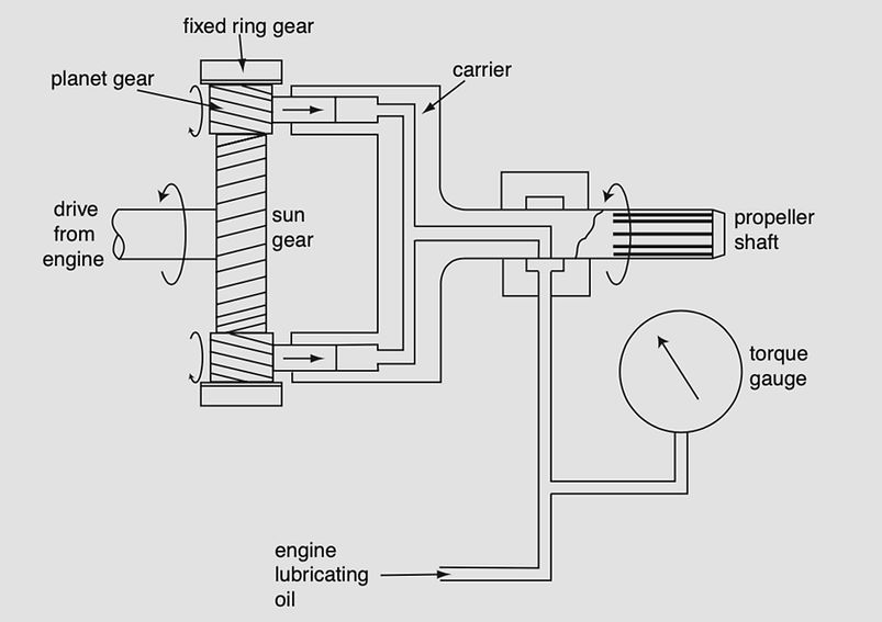
Torque meter
The function of the torque meter is to measure and indicate the power developed by a turbo-propeller engine. The turning moment, or torque, delivered to the propeller through the reduction gearing is proportional to the horsepower developed, which is the product of the torque and the propeller rpm.
In the example of a torque meter system shown in Figure, the reduction gearbox between the engine and the propeller uses a type of gearing known as sun and planet, or epicyclic. A large gear wheel, with helical teeth, drives smaller helical-toothed gear wheels surrounding it. These are the sun and planet wheels from which the name of the system is derived. The planet wheels rotate within a fixed ring gear and are carried in a drum attached to the propeller shaft, thereby transmitting rotation to the propeller shaft.
The torsional force of the engine turning the propeller is transmitted through the planet gears, the helical teeth of which transfer some of that force into an axial direction. The shafts of the planet gears form pistons that fit into cylinders machined in the carrier drum. These cylinders are connected to an enclosed hydraulic system, supplied with oil from the engine lubricating system and connected to a pressure gauge.
Axial movement of the sun gears is restrained by the hydraulic system, but the greater the torsional force, and consequent axial force, the greater the hydraulic pressure created. The gauge reading is usually calibrated to read torque in ft lb and can be used to calculate the brake horsepower (bhp) being delivered to the propeller using the formula bhp = TNK, where T is the torque in ft lb, N the engine rpm and K a constant (2p/33 000).
In some systems the gauge may also show negative torque, the undesirable condition that exists when the propeller is windmilling and tending to drive the engine. The torque meter output is used in some turbo-propeller systems to automatically operate the propeller feathering mechanism in the event of engine failure and excessive negative torque.
An alternative type of torque measuring system makes use of the fact that, under torsional loading, the propeller drive shaft twists. Strain gauges attached to a torque ring mounted on the engine/propeller drive shaft twist and deform with the shaft as torque increases. These produce a small elec- trical signal that varies according to the deformation of the strain gauges and is amplified to actuate the torque meter on the flight deck.
The torque meter gauge scale may incorporate coloured arcs. A green arc indicates the normal operating range of positive torque, a yellow arc indi- cates negative torque and red radial lines or arcs indicate maximum and minimum torque limits or ranges.
TORQUE METER SYSTEM
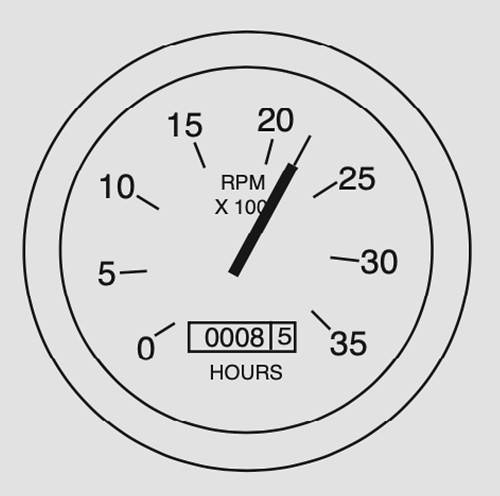
Flight hour meter
An hour meter incorporated in the piston engine tach- ometer display. It is important for routine servicing, inspection and com- ponent life to have a record of the number of flight hours accumulated by the aircraft. In light general aviation aircraft this is often achieved by a meter activated only when the engine is operating at cruise rpm.
For example, if the normal cruise rpm is 2200 it follows that the engine will complete 132 000 revolutions in one hour at cruising speed. Thus, for each 132 000 revolutions the flight hour meter progresses by one unit. Such a meter suffers from the obvious limitation that it does not record flight times at other than cruise rpm. However, for aircraft that operate at this speed for all but take-off and landing, this is adequate and has the advantage of being independent of aircraft electrical power.
A slightly more sophisticated system is operated by an electric clock, powered from the aircraft electrical system and activated by the landing gear `weight-on' or `squat' switch. This system truly records flight time, since the switch supplying power to the clock only closes when aircraft weight is off the landing gear and the battery master switch is closed. This type of flight hour recorder is known as the Hobbs meter.
Fuel consumption gauge
It is important for the flight crew to be aware of the rate at which fuel is being consumed in flight in order to calculate range, endurance and economy. This information is vital to the operation of automated thrust and flight control systems. In large gas turbine powered transport aircraft the measurement of fuel flow is made by relatively complex flow metering systems that are capable of integrating the flow rate with time to compute and display both rate of fuel flow and the total fuel consumed. In smaller, short range transports, particularly those powered by piston engines, it is usual to measure only fuel flow rate using less sophisticated devices.
Fuel flow is ideally measured in terms of mass flow rather than volumetric flow, since it is the mass of fuel consumed that determines the power output of an engine. Mass per unit volume varies with the density of the fuel, which in turn varies with its temperature.
Thus, if fuel flow is measured in terms of volumetric rate (gallons or litres per hour) a further calculation is necessary, taking temperature into account, in order to determine the mass flow rate. In short range aircraft this is less important, but in long range transports the flowmeter calibration usually takes fuel temperature into account and computes mass flow rates. Mass flow is usually measured in pounds (lb) or kilograms (kg) per hour.
Fuel flow and pressure
With a continuous flow fuel-injected piston engine the rate of fuel flow to the injectors is proportional to the fuel supply pressure. In piston-engine aircraft that are equipped with direct fuel injection systems it is not uncommon for the fuel pressure gauge to be calibrated to indicate fuel flow rate as well as fuel pressure.
Since such aircraft are not usually long range types it is adequate for the fuel flow indication to be volumetric, in gallons per hour or litres per hour. An example of a fuel pressure gauge calibrated to serve also as a flowmeter is shown in Figure. It will be noted that the calibration indicates the fuel flow rates for various power settings (e.g. cruise, take-off and climb).

FUEL PRESSURE GAUGE/FLOWMETER
Vane-type flowmeter
The principal disadvantage of the combined pressure gauge/flowmeter is that it will provide erroneous indications if the fuel pressure is artificially high. Suppose, for instance, that an injector has become partly blocked. The fuel being consumed by the engine will be less, because of the blockage, whilst the fuel supply pressure will increase because of it. Consequently, the fuel flow indication would be falsely high.
To measure actual flow rates it is necessary to place a device in the fuel supply line to the engine which will convert fuel flow into mechanical movement and transmit a signal to a fuel flow gauge in the cockpit. A simple type of flow measuring device, used in some piston engine and smaller gas turbine engine aircraft, is shown in Figure.

VANE TYPE FLOW METER
Fuel is directed through a volute chamber in which there is a spring- loaded vane. The action of the fuel pressing on the flat vane causes it to rotate against the force of a coil spring until the gap between the edge of the vane and the inside of the volute chamber no longer impedes fuel flow.
The rotation of the vane is transmitted to a fuel flow gauge in the cockpit by means of a synchro system. The greater the fuel flow, the more the vane will be deflected against the force of the coil spring before the gap is sufficiently wide.
To protect against failure of the vane or other blockage in the volute chamber, a lightly loaded bypass valve will open in the event of the differential pressure across the chamber exceeding a preset value, thereby maintaining fuel flow to the engine.
Integrated flowmeter
Larger, long-range, turbine-powered transports employ a more complex type of fuel flow meter that is much more accurate than the foregoing systems and which integrates the measured flow rate with time, either mechanically or electronically, to compute and indicate fuel consumed as well as fuel flow. An example of the fuel flow measuring system is shown in Figure.
The flowmeter is situated in the high pressure fuel supply to the engine and contains an impeller driven at constant rotary speed by an a.c. synchronous motor. Fuel entering the flowmeter passes through the impeller, which imparts a swirling motion to the fuel flow.
The flow then enters a turbine where the force of the swirling fuel striking the turbine vanes drives the turbine to rotate in the same direction as the impeller rotation. The rotary motion of the turbine is restrained by a coil spring attached to the turbine shaft. As flow rate increases, the force of the swirling fuel acting on the turbine vanes increases, rotating the turbine further against the spring.

INTEGRATED FLOWMETER
The rotary motion of the turbine shaft is sensed by a low voltage transformer (LVDT), which produces an output voltage proportional to the amount of rotation. This output voltage forms the signal transmitted to the fuel consumption display, which is typically a digital readout in kilograms or pounds of fuel consumed.
The signal also operates a servo-motor, which positions the pointer of an analogue fuel flow gauge, showing fuel flow in kilograms or pounds per hour. The two displays are often on the same instrument and an example is shown in Figure.

FUEL FLOW AND FUEL USED METER
Failure of the integrated flowmeter impeller or turbine will not impede the fuel flow to the engine, but will obviously render the gauge readings useless. Failure is typically indicated by a warning flag on the instrument display. The flowmeter circuitry may also incorporate a low fuel flow warning.
Fuel quantity measurement
In addition to knowing the rate at which fuel is being consumed, and the cumulative total of fuel consumed, it is clearly essential that the pilots are also aware of the quantity of fuel remaining in the aircraft tanks and so some form of tank gauging is necessary.
One of the simplest forms of aircraft fuel tank gauge ever devised comprised a float-operated vertical dipstick, which protruded through a hole in the top of the tank at a location visible from the cockpit. The extent of dipstick protruding directly indicated the quantity of fuel remaining in the tank.
Resistive Fuel Quantity Measurement
Such a system as that described above is obviously impractical for a large transport aircraft where the pilots and the automated systems need to know the exact quantity of fuel in each tank. However, in smaller aircraft a system of remote tank contents indication is often employed which does not differ greatly in principle from the float-operated dipstick.
A float in the tank operates the wiper of a potentiometer, the output of which drives a moving coil instrument. As fuel level in the tank varies, the float moves up or down accordingly and operates the potentiometer, which is supplied with low voltage from the aircraft electrical system.
The potentiometer signal causes the moving coil in the indicating gauge to position itself according to the strength of the signal, positioning the gauge pointer against a calibrated scale to show tank contents in gallons or litres.

RESISTIVE TANK CONTENTS MEASUREMENT
This system of measuring the amount of fuel remaining in a tank suffers from a number of potential inaccuracies and is only suitable for use in the relatively small fuel tanks of light general aviation aircraft. Movement of fuel in the tank, due to changes of aircraft attitude or acceleration, will cause the float to move up or down and the system will falsely indicate the fuel quantity in the tank.
Furthermore, since the system can only measure the level of fuel in the tank, it will give a false indication of quantity if the level changes due to temperature change. As both of these causes of inaccuracy are limited in the small tanks of light aircraft, they are generally acceptable.
Additionally, the system is only capable of indicating the volume of fuel contained in the tank, computed from the fuel level and the known tank dimensions, so the associated fuel tank contents gauge must be calibrated in litres or gallons, rather than the preferred kilograms or pounds.
Capacitive fuel quantity measurement
The fuel tank contents in large aircraft, with a significant number of correspondingly large tanks, are measured by a system that uses the electrical capacitance of the fuel to determine the exact quantity of fuel in each tank and to indicate it in terms of mass rather than volume.
A capacitor is an electrical device consisting basically of two conducting plates separated by a resistive medium known as a dielectric. Such a device is capable of storing an electric charge and this property is known as capacitance. The principle of operation of a capacitor is shown in Figure.

CAPACITANCE PRINCIPLE
Capacitance, the ability to store an electric charge, depends upon the surface area of the capacitor plates and the permittivity of the medium separating the plates. Permittivity is also sometimes referred to as the dielectric constant of the separating medium. It is usually measured as a relative value, where air has a permittivity of 1.00, so other media are assigned a relative permittivity indicating the capacitance they offer relative to air. Aviation kerosene, for example, has a relative permittivity of 2.10.
The capacitance or `charge-holding capability' of a capacitor is the ratio between the charge supplied and the potential difference between the two plates and is measured in picofarads (pF). The strength of the discharge current from a capacitor will depend upon its capacitance and the rate of change of the supply voltage.
The latter is a constant given a constant frequency a.c. supply and the capacitance, as we have seen, is dependent upon the permittivity of the medium. Suppose two identical capacitors are supplied with 6 V a.c. at a frequency of 400 Hz and one is placed in air whilst the other is placed in aviation kerosene. The capacitor with air separating its plates will produce a lower discharge current than the one with fuel separating its plates.
The capacitive probe inserted into an aircraft fuel tank is basically two open-ended tubes, one inside the other. The tubes act as the capacitor `plates', separated by air or fuel, depending upon the depth of fuel in the tank. The concept is illustrated in Figure.
In Figure (a) the tank is empty and the separating medium is air, with a relative permittivity of 1.00. For the sake of simplicity, let us assume that the capacitance of the probe is 100 pF.
In Figure (b) the tank is filled with aviation kerosene with a permittivity of 2.10, so the capacitance of the probe will now be 210 pF, an increase of 110 pF, and its discharge current, when it is supplied with constant frequency a.c., will be 2.10 times greater than when the tank was empty.
If the tank is half full, as shown in Figure (c), the increase in capacitance over the `tank empty' value will be half as much, i.e. 55 pF. Thus, the capacitance of the probe will be 155 pF and the discharge current will be 1.55 times the empty value. From this it can be seen that the tank fuel level is accurately represented by the probe discharge current, and this is used to operate the tank contents gauge.
Compensation for movement of fuel in the tank due to aircraft attitude or acceleration changes is easily made by inserting several probes at different locations within the tank and `averaging' their outputs to give a mean reading. Smaller tanks typically have two probes, whereas larger ones may have as many as six.

EFFECT OF FUEL ON CAPACITANCE
A simplified capacitive tank contents measuring system is shown in Figure. The low voltage alternating current supply to the system is from a power transformer to the fuel tank capacitor probe and to a reference capacitor in parallel with it. Because the fuel tank should never be completely empty, the charge from the probe will always be greater than the constant value of the reference capacitor.
The higher the fuel level in the tank, the greater the difference and it is this potential difference that actuates the voltmeter, which is calibrated to read tank contents. A complete capa- citive system is more complex than this, since it contains circuitry that allows the indicator gauge to be `zeroed', that is the maximum and minimum readings to be adjusted for purposes of calibration.

SIMPLE CAPACITIVE GAUGING SYSTEM
Fuel quantity by weight
The observant reader will have noted that, so far, all references have been to the measurement of fuel level in the tank, but it is ideally required that the measurement of fuel contents should be by weight. We have already established that fuel will expand as its temperature increases and the level of fuel in the tank will increase, whilst the important factor, its weight, remains the same. Therefore, if the gauges are calibrated to show quantity by weight, one would expect them to be in error.
However, the increase in volume with no change in weight means, by definition, that the fuel density has decreased. The reduction in density reduces the permittivity of the fuel and so the capacitance of the probe is reduced. This reduction almost exactly mirrors the increase in capacitance due to the higher level of fuel and the two effectively cancel each other out. Thus, the capacitance method of fuel tank measurement automatically compensates for changes in fuel density due to temperature changes.