Distance Measuring Equipment (DME)
Introduction
Distance Measuring Equipment (DME) is is a short/medium range navigation system, which operates of the principle of a secondary radar system that enables an aircraft to establish its range from a ground station.
Distance measuring equipment (DME) is used in conjunction with other systems, e.g. VOR and ILS, to provide accurate navigation fixes.
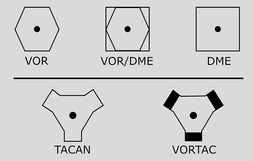
VHF Omni-range (VOR) beacon provides magnetic bearings and Distance measuring equipment (DME) provides slant ranges for their respective stations. With bearing and range information being available, the pilot is able to determine its position using the standard ICAO approved RHO-THETA short range, “Line of Sight” navigation aid (Rho = range; Theta = bearing).
Hence in some cases the DME and VOR stations are combined together.
Radar principles
The word Radar stands for RAdio Detection And Ranging earlier it used pulses waves for its operation but subsequently continuous wave (CW) techniques were also developed.
There are two kinds of radar system used primary radar and secondary radar.
Primary Radar
A Primary Radar uses pulses of radio energy reflected from a target (cloud or aircraft) i.e. it uses one frequency throughout. It was initially use of radar was to locate aircraft and display their range and bearing on a monitor. A pulse was radiated towards the target and the strength of the returned energy is measured and used to determine the range of the target. The antenna used is directional as it provides omnidirectional information.
Primary radar has its disadvantages, one of which is that the amount of energy being transmitted is very large compared with the amount of energy reflected from the target.
Secondary Radar
A Secondary Radar transmits pulses on one frequency, but receives on a different frequency i.e. the object transmits its own energy. It is a system utilizing an interrogator and transponder; the transponder can be located in the aircraft or on the ground. It was initially used for Identification Friend or Foe (IFF) which differentiate between friendly aircraft and ships.
The principles of secondary radar now have a number of applications including distance measuring equipment (DME).

PRIMARY RADAR AND SECONDARY RADAR
Distance Measuring Equipment (DME)
The DME navigation aid contains a transponder (receiver and transmitter), which operated on secondary radar system principle operating between 960 and 1215 MHz in the UHF band.
There is always a difference of +/- 63 MHz between the interrogator and transponder frequencies. Transmission is in the range 1025 to 1150 MHz; receiving is in the range 962 to 1215 MHz; channel spacing is 1 MHz, this provides 252 spot frequencies or channels.
The channels are numbered 1 to 126X and 1 to 126Y. The emission code for DME is P0N
TACAN is a military system which gives both range and bearing with respect to a fixed beacon. The ranging part of TACAN has the same characteristics as civil DME. There are, however, more channels available with TACAN since it utilizes an extended frequency range of 962-1213 MHz.
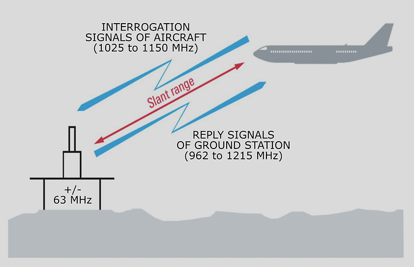
DME INTERROGATION AND REPLY
The DME has the following functions
-
It provides very accurate slant range, a circular position line and in conjunction with another DME, or a co-sited VOR, two position line fixes.
-
It integrates the change of slant range into ground speed and elapsed times when the aircraft is fitted with an appropriate computer.
-
It permits more accurate flying of holding patterns and DME arcs.
-
It provides range and height checks when flying non-precision approach procedures, e.g.
-
It locator only and VOR let-downs.
-
It indicates accurate ranges to the runway threshold, and heights for range, when flying an ILS/DME procedure.
-
It facilitates radar identification when the pilot reports his VOR/DME position.
-
It facilitates the separation and control of aircraft in non-radar airspace, based upon a VOR/DME fix reported by individual aircraft.
-
It is the basis for a simple Area Navigation (RNAV) system when the appropriate computerization is fitted.
-
It provides accurate range inputs into the more complex and accurate RNAV systems; twin, self-selecting DME/DME are used.
DME operation
DME is a secondary radar system providing slant range by pulse technique. However if the aircraft is above the DME station it will indicate altitude above DME station.
The difference between computed slant range and actual ground distance increases the higher and closer an aircraft gets in relation to the DME. As a general rule the difference becomes significant when the aircraft is at a range which is less than 3 × height. When the aircraft is directly over the DME (0 NM ground distance), it will indicate the aircraft’s height in nautical miles. There is a small cone of confusion over a DME, plus range indications continue to be computed as the equipment has a 10 second memory circuit.
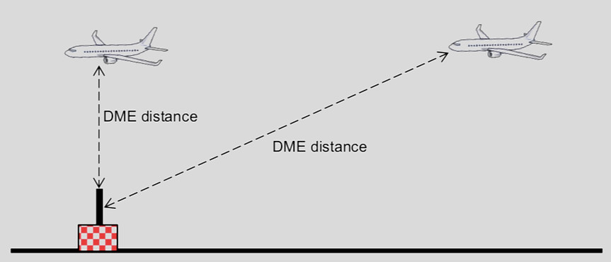
DISTANCE MEASURING EQUIPMENT (DME) SLANT RANGE
The aircraft equipment radiates omni-directional pair of pulses, each of 3.5 µs duration, on the carrier frequency of the ground transponder to the DME navigation aid. The interrogator generates a pulse-pair repetition rate between 5 and 150 pulse-pairs per second. Simultaneously the interrogator’s receiver starts a Range Search.
Secondary signals from the ground transponer are then transmitted back to the aircraft, after a delay of 50 μs, at a frequency that is +/- 63 MHz removed from the interrogation frequency.

BASIC DISTANCE MEASURING EQUIPMENT (DME) BLOCK DIAGRAM
Since we know the speed of radio wave propagation, the interrogator can calculate the distance to the DME navigation aid. Range is given by:
R = (T-50)/12.359
Where:
R is the slant range distance in nautical miles to or from the beacon;
T is the time in microseconds (μs) between transmission of the interrogation and reception of the reply.
The constants in the equation are 50 μs corresponding to the fixed beacon delay, it takes 6.18 μs for 1 nautical mile, hence 12·359 μs being the time taken for r.f. energy to travel 1 nautical mile and return.
A 3 letter call sign station identification(Morse code) is transmitted every 30 seconds at an audio tone of 1350 Hz, usually in conjunction with an associated VOR.
During the ident period the random pulses are replaced by regularly spaced pulses keyed with the station identification letters. This means that range information is not available during the ident period. However the aircraft equipment has a 10 second memory circuit to continue displaying the range obtained.

WORKING OF DISTANCE MEASURING EQUIPMENT (DME)
The DME ground station responds to the interrogations of 50–100 aircraft; these all send their interrogations at the same DME station frequency.
Since the ground replies to all multiple aircraft, it is important for the interrogator to identify its own signal, hence each aircraft’s interrogator is programmed to transmit its paired pulses at random intervals i.e. the transmission sequence of pulses is irregular or jittered. This differentiates its pulses from all the others.
DME Interrogations and Reply
The full TACAN interrogation frequency range is 1025-1150 MHz with 1 MHz spacing. Thus the interrogation will be one of 126 possible frequencies depending on the channel selected. The r.f. is keyed by pulse pairs. The timing, which is dependent on channel selection, X or Y.
The pulse width is 3.5 μs and for X channel the timing between two pulses is 12 μs and for Y channel the timing between two pulses is

X and Y Channel Arrangements
There are 126 interrogation and 252 reply frequencies, since the reply frequency is 63 MHz above or below the interrogating frequency. The channel spacing is 1 MHz for both interrogation and reply.
The TACAN channels are numbered 1X, 1Y, ... 26X, 126Y. For example channel 20X, say, corresponds to an interrogation at 1044 MHz and a reply at 981 MHz, while channel 16Y, say, corresponds to an interrogation at 1140 MHz and a reply at 1077 MHz.
For civil DME beacons the 52 channels from 1-16, X and Y, and 60-69, X and Y, are not used since DME is used in conjunction with VOR and ILS and they have only 200 channels and not 252. Other reason is to avoid overlap and any possible interference with the ATC transponder frequencies of 1030 and 1090 MHZ.
DME Equipment
There are two independent DME systems, comprising antennas and interrogators. The DME antennas are L-band blades, located on the underside of the aircraft fuselage, the antenna is dual purpose in that it is used for both transmitting and receiving.

DME ANTENNA
The interrogators are located in the equipment bays and provide three main functions:
-
Transmitting
-
Receiving
-
Calculation of distance to the selected navigation aid
The interrogator operates in several modes:
-
Standby
-
Search
-
Track
-
Scan
-
Memory
-
Fault
-
Self-test.
Standby
When the aircraft is out of range of the beacon to which the airborne DME is tuned the system or is first powered up, it enters the standby mode; transmissions are inhibited, the receiver and audio are operative; This state inhibits interrogations until such time as the aircraft is within range and signals are received. The DME display is four dashes to indicate no computed data (NCD). The receiver monitors pulse-pairs received from any local ground stations. This mode is also called as signal-activated search.
However there is a problem associated with the standby circuit that the interrogations only commence when signals are detected. When a sufficient number of interrogating aircraft are within range of the beacon there is no problem, since another aircraft coming within range will receive all the replies and thus begin to interrogate. If, however, we consider the beacon having just come on line or the first flight, after a quiet period, approaching the beacon, we have a chicken-and-egg situation: the beacon will not reply unless interrogated; the interrogator will not interrogate unless it receives signals.
As we have seen that the station identification pulse is radiated every 30 sec, this means an aircraft may have to wait 30 sec, perhaps more in weak signal areas, before coming out of auto standby.
Hence to solve the above issue the beacon is made to transmit pulse pairs even in the absence of interrogations, such transmissions from the ground beacon are known collectively as "squitter" to distinguish them from replies. When the random squitter pulse pairs are received the airborne equipment starts to interrogate.
A beacon must transmit randomly distributed pulse pairs at a repetition rate of at least 700; this minimum rate includes distance replies as well as squitter. Beacons which supply a full TACAN service, i.e. range and bearing, must maintain a rate of 2700 pulse pairs per second. In order to achieve this during ident an equalizing pair of pulses is transmitted 100 μs after each identity pair. A range-only DME beacon can also transmit at a constant duty cycle of 2700 pulse pairs per second.
Search
When sufficient pulse-pairs are received, the interrogator enters the search mode. The transmitter now transmits pulse-pairs and monitors any returns; synchronous pulse-pairs are converted from time into distance and the system enters the track mode.
Track
In the track mode Distance to the navigation aid will now be displayed on the DME indicator.
Scan
The scan mode has two submodes:
-
directed scanning for multiple navigation aid tuning; up to five stations can be scanned in accordance with a predetermined area navigation auto-tuning programme.
-
Alternatively, free scanning occurs for any DME navigation aids within range.
Memory
If replies are lost an interrogator will not immediately revert to search or auto standby but will enter its memory condition; this may be one of two types, either static or velocity.
With static memory the readout is maintained steady, whereas with velocity memory the readout continues to change at its last known rate. Memory time will normally lie between 4 and 12 s.
If, during memory, replies are re-acquired, the equipment will continue tracking; thus the pilot will have been spared a false warning. At the end of memory, if there are no signals at all being received, auto standby will ensue; otherwise the equipment will commence searching.
Self Test
If the system detects any fault conditions, the distance display is blanked out. Self-test causes the system to run through a predetermined sequence causing the indicators to read: blank, dashes no computed data (NCD) and 0.0 nm.
DME outputs can be displayed in a variety of ways. These displays include dedicated readouts, electronic flight instrument systems (EFIS), combined panels/ transceivers (for general aviation) and radio distance magnetic indicators (RDMI).
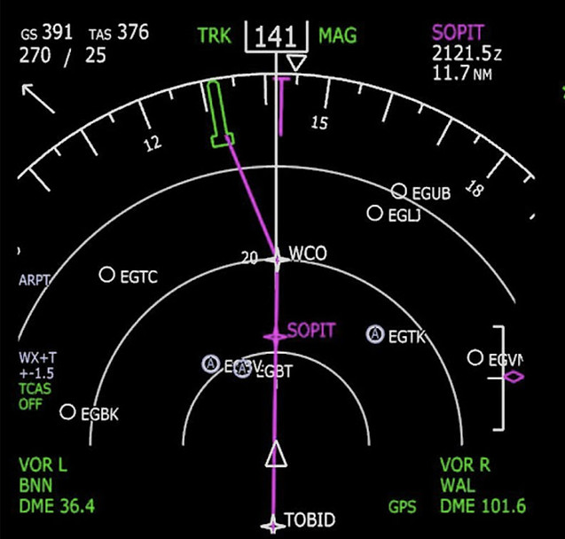
DME INDICATIONS ON EFIS
Navigation Using Distance Measuring Equipment (DME)
Navigation using DME can be achieved by using one of the two methods
-
Rho–Theta fixes
-
Rho–Rho fixes
The rho–theta fixes navigation can be achieved from a single navigation aid by co-locating VOR and DME stations, while the rho-rho fixes navigation can be acheived by using two DME navigation aids.
When selecting a co-located VOR-DME navigation aid , as the DME frequency is paired with the VOR frequency the crew only needs to tune into the VOR frequency; the DME frequency is automatically selected.
The table below indicate the relative position and the paring of frequencies of VOR/DME stations along with the identification signals.

VOR AND DME CO-LOCATED FREQUENCY PARING
TACAN (tactical air navigation) was introduced in the US for military aircraft, which is essentially a DME transponder to which directional information has been added and operated in the 962–1215 MHz (UHF) band. Thus both both distance and bearing are transmitted on the same frequency.
TACAN navigation aids which are co-located with VOR navigation aids they are identified on navigation charts as ‘VORTAC’. This allows both military and commercial aircraft can share the VORTAC facility.
The military aircraft obtain their distance and bearing information from the TACAN part of the VORTAC; commercial aircraft obtain their distance information from the TACAN and bearing information from the VOR part of the TACAN.