
Aircraft Batteries
Introduction
The basic function of any electrical cell is the conversion of chemical energy into electrical energy.
The cells can be considered as a chemical means of storing electrical energy.
Electrons are removed from the (positive) cathode and deposited on the (negative) anode. The electrolyte is the physical means of migration between the cathode/anode. The attraction of electrons between cathode/anode creates a potential difference across the cell; the cathode/anode is attached to external terminals for connection to the equipment or system. Material types used for the cathode/anode and electrolyte will determine the cell voltage.
Cells are categorised as
-
Primary (where they can only be used once)
-
Secondary (where they can be recharged)
Open Circuit Voltage (OCV) & Closed Circuit Voltage (CCV)
The Voltage measured when no load applied to the battery is called as Open Circuit Voltage (OCV) and the voltage measured when load is applied to the battery is called as Closed Circuit Voltage (CCV). The OCV is always greater than the CCV as no current flows from the battery.
For example the OCV of a battery maybe 13.5V; however when a small amount of load is applied the voltage drops to 12V. This battery will generally be called as a 12V battery.
Internal Resistance
The resistance present inside the battery while connected to a load is called as Internal Resistance (IR). IR is determined by the load applied and the batteries state of charge. Batteries IR is equal to the difference between the OCV & CCV, divided by applied load amperage.
IR = (OCV-CCV)/load amperage.
A batteries IR becomes greater as the batteries become discharged, since the CCV drop and OCV nearly remains constant unless the battery is fully discharged. The difference between them increases and hence the IR increases.
Survival Hacks for Student Species
Tricky Question :
If batteries were students, what would their OCV and CCV reveal about their study habits?
Smart Answer:
OCV is the confidence before the exam: "I know everything!" CCV is the reality when the exam starts: "Wait… what was that formula again?"
REMEMBER: OCV IS ALWAYS GREATER THEN CCV
Types of Aircraft Battery
Aircraft batteries are usually identified by the material used for the plates. The two most common types of battery used are
-
Lead Acid Battery
-
Nickel Cadmium Battery
Most small private aircraft use lead acid batteries. Most commercial and corporate aircraft use nickel-cadmium
(Ni-Cd) batteries. However, other lead acid types of batteries are becoming available, such as the valve-regulated lead-acid (VRLA) batteries.
The battery best suited for a particular application depends on the relative importance of several characteristics, such as weight, cost, volume, service or shelf life, discharge rate, maintenance, and charging rate.
Aircraft batteries are used for many functions like
-
Ground Power
-
Emergency Power
-
Improving DC bus stability
-
Fault clearing
Lead-Acid Batteries
Lead Acid cell consist of lead compound plates immersed in a solution of sulphuric acid and water, which is the electrolyte. The positive plate is filled with Lead Peroxide, negative plate is filled with pure spongy lead and an electrolyte consisting of mixture of 30 % sulphuric acid and 70 % water by volume to achieve a specific gravity of 1.2.
Each cell has an OCV of approximately 2.1V when fully charged, and CCV is approximately 2V.
Aircraft Lead- Acid batteries are generally rated at 12V or 24V; hence have 6 or 12 cells connected in series.
Construction of Lead Acid Battery
Each cell of the storage battery has a positive and negative plates arranged alternatively and insulated from each other by separator. Each plate consists of a framework called as grid and the active material is held inside the grid. The grid is made of 90 % lead and 10 % antimony. the purpose of antimony is to harden the lead and make is less susceptible to chemical reaction. Other metals like silver is also used to increase durability.
The plates are made up by applying a lead compound to the grid. The paste is mixed to a proper consistency with dilute sulphuric acid, magnesium sulfate or ammonium sulfate and is applied to the grid.
The plaster for positive plate is made up of large portion of red lead and a small amount of litharge. The plaster for negative plate is made up of large portion of litharge and a small amount if red lead. In compounding negative plate an material called expaner is added, which is chemically inert and consist of 1% of the mixture. Its purpose is to prevent the loss of porosity of the negative plate. Some of the expander material used are lampback, barium sulfate, graphit, fine sawdust and ground carbon.
After active material is applied it is dried until the paste is harden. Then they are given forming treatment where positive plates are connected to the positive terminal of a charger and the negative plate plus one to the negative terminal of the charger. They are then placed in the solution of sulphuric acid and water (electrolyte) and charged slowly over a long period of time.
A few cycles of charging and discharging convert the lead compound into active material. The positive plates formed are Lead peroxide and chocolate brown in colour and negative plate formed are spongy lead of pearl gray colour. After forming the plates are washed and dried and assembled into plate groups by connecting similar plates to a common terminal plates.
Each plate is made with a lug at the top to which the plate strap is fused. All the positive lug are connected together and all the negative are connected together. We have one extra negative plate as compared to the positive plate; the negative plate is placed at the start and end, hence a negative plate is placed on each side of the positive plate. This helps in chemical reaction being evenly distributed on both sides of the positive plate.
The separator used in lead acid batteries are made of fibreglass, rubber or other insulating material. Their purpose is to keep the plates separated thus preventing an internal short circuit. The material of the separators must be very porous so that it will offer minimum resistance to the flow of current.
When the cell elements are assembled, they are placed in a cell container, which is made of hard rubber or plastic.

Lead Acid Battery Construction
Chemical action or operation
During discharging the sulphuric acid in the electrolyte breaks up into hydrogen ions carrying a positive charge and sulphate ions carrying negative charge. The sulphate ions combines with the lead plate and form Lead sulphate. At the same time they give up their negative charge thus creating an excess of electrons on the negative plate.
The hydrogen ions go to the positive plate and combine with oxygen of the lead peroxide, forming water, and during the process they take electrons from the positive plate. The lead peroxide combine with some of the sulphate ions to form lead sulphate on the positive plate.
The resultant action is that the positive plate is deficient of electrons and the negative plate has excess of electrons. As the plates are connected externally by a conductor, the current flows through it until both plates are coated with lead sulphate and no further chemical reaction can take place.
During the charging process, an external supply is connected to the battery. the positive plate of the battery is connected to the positive supply lead and the negative plate of the battery is connect to the negative supply. As the current flows in the opposite direction the sulphate ions are driven back into the electrolyte where they combine with hydrogen ion forming sulphuric acid. The plate returns to their original position of lead peroxide and spongy lead.
As the cell is charged, the sulphuric acid (H2SO4) concentration increases and becomes highest when the cell is fully charged. Likewise, when the cell is discharged, the acid concentration decreases and becomes most dilute when the cell is fully discharged.

LEAD ACID BATTERY CHEMICAL REACTION
Types of Lead Acid Batteries
Dry Charged Cell Lead Acid Batteries
Dry charged cell lead-acid batteries, also known as flooded or wet batteries, are assembled with electrodes (plates) that have been fully charged and dried. The electrolyte is added to the battery when it is placed in service, and battery life begins when the electrolyte is added.
When flooded (vented) batteries are on charge, the oxygen generated at the positive plates escapes from the cell. Concurrently, at the negative plates, hydrogen is generated from water and escapes from the cell. The overall result is the gassing of the cells and water loss. Therefore, flooded cells require periodic water replenishment.
Valve-Regulated Lead-Acid Batteries (VRLA)
VRLA batteries contain all electrolyte absorbed in glass-mat separators with no free electrolyte and are sometimes referred to as sealed batteries.The electrochemical reactions for VRLA batteries are the same as flooded batteries, except for the gas recombination mechanism that is predominant in VRLA batteries. These types of battery are used in general aviation and turbine powered aircraft and are sometimes authorized replacements for Ni-Cd batteries.
When VRLA batteries are on charge, oxygen combines chemically with the lead at the negative plates in the presence of sulphuric acid to form lead sulphate and water. This oxygen recombination suppresses the generation of hydrogen at the negative plates. Overall, there is no water loss during charging.
A very small quantity of water may be lost as a result of self-discharge reactions; however, such loss is so small that no provisions are made for water replenishment. The battery cells have a pressure relief safety valve that may vent if the battery is overcharged.
For this reason, sealed lead-acid cells are often called “valve-regulated lead-acid” (VRLA) cells.
Temperature Effects and Limitations
Lead-acid batteries generally are rated at 25°C (77°F) and operate best around this temperature. Exposure to low ambient temperatures results in performance decline, whereas exposure to high ambient temperatures results in shortened life.
The lower temperature limit is dictated by the freezing point of the electrolyte. The electrolyte freezing point varies with acid concentration. The minimum freezing point is a chilly 70°C (95°F) at a specific gravity (SG) of 1.30. Since fully charged batteries have SGs in the range of 1.28 to 1.33, they are not generally susceptible to freezing even under extreme cold conditions.
However, when the battery is discharged, the SG drops and the freezing point rises. At low SG, the electrolyte first will turn to slush as the temperature drops. This is because the water content freezes first, gradually raising the SG of the remaining liquid so that it remains unfrozen. Solid freezing of the electrolyte in a discharged battery requires temperatures well below the slush point; a practical lower limit of 30°C is often specified.
Solid freezing can damage the battery permanently (i.e., by cracking cell containers), so precautions should be taken to keep the battery charged or heated when exposed to temperatures below 30°C.
The upper temperature limit is generally in the range of 60 to 70°C. Capacity loss is accelerated greatly when charged above this temperature range due to vigorous gassing and/or rapid grid corrosion. The capacity loss generally is irreversible when the battery is cooled
Service Life
The service life of a lead-acid aircraft battery depends on the type of use it experiences (e.g., rate, frequency, and depth of discharge), environmental conditions (e.g., temperature and vibration), charging method, and the care with which it is maintained. Service lives can range from 1 to 5 years, depending on the application.
Ni-Cd Battery
The Ni-Cd batteries in charged state is made up of Nickel oxyhydroxide for the positive plate and Metallic Cadmium for the negative plate and during discharge the positive plate is converted to Nickel hydroxide and negative plate to Cadmium hydroxide. The electrolyte is made up of 70% distilled water and 30 % potassium hydroxide to achieve a specific gravity of 1.3. Generally Specific gravity of Ni-Cd battery is in the range of 1.24 to 1.32.
Each Cell has an OCV of 1.28V & the CCV ranges between 1.2 to 1.25 V as it depends on the battery temperature, the length of the time battery is last charged and the discharge current applied.
A typical 24V Ni-Cd Battery consist of 19 or 20 cells connected in series.
Aircraft that are outfitted with Ni-Cd batteries typically have a fault protection system that monitors the condition of the battery. The battery charger is the unit that monitors the condition of the battery and the following conditions are monitored.
1. Overheat condition
2. Low temperature condition (below –40 °F)
3. Cell imbalance
4. Open circuit
5. Shorted circuit
If the battery charger finds a fault, it turns off and sends a fault signal to the Electrical Load Management System (ELMS).
Construction of Ni-Cd Battery
Each cell of the battery consist of negative and positive plate, separator, electrolyte, cell container, cell cover and a vent cap.
The plates are made from sintering metal plaques impregnated with the active material for the positive and negative plates. Sintering is a process of heating finely divided metal particles weld together where they are in contact with other particles, which results in making a porous material.
The sintered material for positive plate is nickel or nickel carbonyl and for the negative plate is cadmium. When the plaques are sintered the result is a porous material that is 80 % to 85 % open volume and 15 % to 20 % solid material. The porous paques is impregnated with nickel salts to make positive plate and cadmium salts to make negative plate.
After plaques have absorbed enough active materials to provide the desired capacity, they are placed in an electrolyte and subjected to an electric current, which converts the nickel and cadmium salts into final form. The plaques are then washed and dried and cut into plates. A nickel tab is welded at a corner of each plate and is the means by which plates are joined together into plate groups.
The separator for Ni-Cd cell is a thin porous multilaminate of woven nylon with a layer of cellophane.
The cell container is a plastic cell jar and a cover which are permanently joined at assembly.
Theory of Operation
As the battery discharges the hydroxide ion from the electrolyte combines with the cadmium in the negative plate, and electrons are released into the plate. The cadmium is converted into cadmium hydroxide during the process. At the same time the hydroxide ion from the nickel oxyhydroxide positive plate goes into the electrolyte carrying the extra electron with it. This the positive plate is deficient of electron and the negative plate is excess of electrons and as conductor is connected current flows through it.
When the Ni-Cd battery is charged the hydroxide ion are forced to leave the negative plate and enter the electrolyte. Thus the cadmium hydroxide of the negative plate is converted back to metallic cadmium. The hydroxide ion from the electrolyte recombine with the nickel hydroxide of the positive plate, and the active material is converted to a higher state of oxidation called nickel oxyhydroxide. This process continues until all the active material is converted.
If the battery is overcharged then the water in the electrolyte will decompose by electrolysis. Hydrogen is released at the negative plate and Oxygen is released at the positive plate.
Since during the reaction the hydroxide ion are added to the electrolyte as rapid as they are removed.For this reason the specific gravity of the electrolyte remains essentially constant at any stage of discharge.
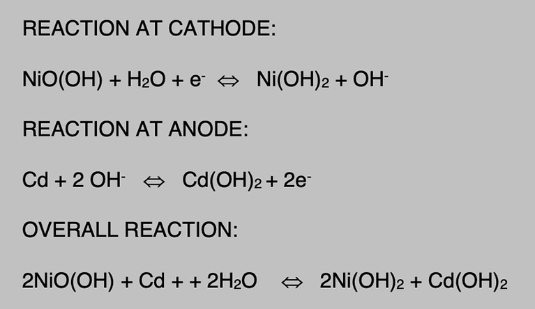
NI-CD BATTERY CHEMICAL REACTION
Types of Ni-Cd Battery
Vented
Vented cells have a flooded electrolyte, and the hydrogen and oxygen gases generated during charging are vented from the cell container.
Recombinant
Recombinant cells have a starved electrolyte, and the oxygen generated from the positive electrode during charging.
The recombination reaction suppresses hydrogen evolution at the negative electrode, thereby allowing the cell to be sealed. Unlike valve-regulated lead-acid cells, recombinant nickel-cadmium cells are sealed with a high-pressure vent that releases only during abusive conditions. Thus, these cells remain sealed under normal charging conditions. However, provisions for gas escape must still be provided when designing battery cases since abnormal conditions may be encountered periodically (e.g., in the event of a charger failure that causes an over current condition)
Battery Charging
Operation of aircraft batteries beyond their ambient temperature or charging voltage limits can result in excessive cell temperatures leading to electrolyte boiling, rapid deterioration of the cells, and battery failure. The relationship between maximum charging voltage and the number of cells in the battery is also significant. This determines (for a given ambient temperature and state of charge) the rate at which energy is absorbed as heat within the battery.
For lead-acid batteries, the voltage per cell must not exceed 2.35 volts.
In the case of Ni-Cd batteries, the charging voltage limit varies with design and construction. Values of 1.4 and 1.5 volts per cell are generally used.
In all cases, follow the recommendations of the battery manufacturer.
Constant Voltage Charging (CP)
The battery charging system in an airplane is of the constant voltage type. An engine-driven generator, capable of supplying the required voltage, is connected through the aircraft electrical system directly to the battery. A battery switch is incorporated in the system so that the battery may be disconnected when the airplane is not in operation. The voltage of the generator is accurately controlled by means of a voltage regulator connected in the field circuit of the generator.
For a 12-volt system, the voltage of the generator is adjusted to approximately 14.25. On 24-volt systems, the adjustment should be between 28 and 28.5 volts. When these conditions exist, the initial charging current through the battery is high. As the state of charge increases, the battery voltage also increases, causing the current to taper down. When the battery is fully charged, its voltage is almost equal to the generator voltage, and very little current flows into the battery.
When the charging current is low, the battery may remain connected to the generator without damage. When using a constant-voltage system in a battery shop, a voltage regulator that automatically maintains a constant voltage is incorporated in the system. A higher capacity battery (e.g., 42 Ah) has a lower resistance than a lower capacity battery (e.g., 33 Ah). Hence, a high-capacity battery draws a higher charging current than a low-capacity battery when both are in the same state of charge and when the charging voltages are equal. The constant voltage method is the preferred charging method for lead-acid batteries.

CONSTACT VOLTAGE CHARGING
Constant Current Charging
Constant current charging is the most convenient for charging batteries outside the airplane because several batteries of varying voltages may be charged at once on the same system. A constant current charging system usually consists of a rectifier to change the normal AC supply to DC. A transformer is used to reduce the available 110-volt or 220- volt AC supply to the desired level before it is passed through the rectifier. If a constant current charging system is used, multiple batteries may be connected in series, provided that the charging current is kept at such a level that the battery does not overheat or gas excessively.
The constant current charging method is the preferred method for charging Ni-Cd batteries as it ensure better cell balance and total battery charge it also prevents possibility of thermal runaway.
Typically, a Ni-Cd battery is constant current charged at a rate of 1CA until all the cells have reached at least 1.55V. Another charge cycle follows at 0.1CA, again until all cells have reached 1.55V. The charge is finished with an overcharge or top-up charge, typically for not less than 4 hours at a rate of 0.1CA.
The purpose of the overcharge is to expel as much, if not all the gases collected on the electrodes, hydrogen on the anode, and oxygen on the cathode; some of these gases recombine to form water that, in turn, raises the electrolyte level to its highest level after which it is safe to adjust the electrolyte levels.
During the overcharge or top-up charge, the cell voltages go beyond 1.6V and then slowly start to drop. No cell should rise above 1.71V (dry cell) or drop below 1.55V (gas barrier broken). Charging is done with vent caps loosened or open. A stuck vent might increase the pressure in the cell. It also allows for refilling of water to correct levels before the end of the top-up charge while the charge current is still on.
However, cells should be closed again as soon as the vents have been cleaned and checked since carbon dioxide dissolved from outside air carbonates the cells and ages the battery.

CONSTANT CURRENT CHARGING
Thermal Runaway
Ni-Cd batteries are capable of performing to its rated capacity when the ambient temperature of the battery is in the range of approximately 60–90 °F. An increase or decrease in temperature from this range results in reduced capacity. Ni-Cd batteries have a ventilation system to control the temperature of the battery. A combination of high battery temperature (in excess of 160 °F) and overcharging can lead to a condition called thermal run away. The temperature of the battery has to be constantly monitored to ensure safe operation. Thermal runaway can result in a Ni-Cd chemical fire and/or explosion of the Ni-Cd battery under recharge by a constant-voltage source and is due to cyclical, ever-increasing temperature and charging current.
One or more shorted cells or an existing high temperature and low charge can produce the following cyclical sequence of events:
1. Excessive current,
2. Increased temperature,
3. Decreased cell(s) resistance,
4. Further increased current, and
5. Further increased temperature
This does not become a self-sustaining thermal-chemical action if the constant voltage charging source is removed before the battery temperature is in excess of 160 °F.
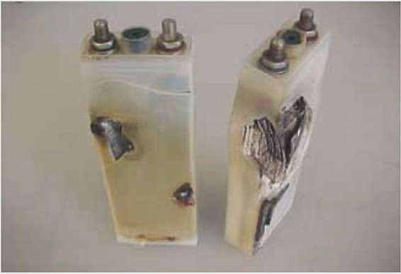
EXAMPLE OF THERMAL RUNAWAY
Cell Imbalance & Deep Cycling
Cell imbalancing occurs during recharging by an aircraft constant voltage charging system. This out of balance condition is caused by difference in temperature or charge efficiency or by varying self discharge rate in the cells. To ensure optimum performance of and battery life any cell imbalance should be corrected through reconditioning of the cells.
To correct a cell imbalance during reconditioning the battery is typically discharged to zero capacity and then recharged. This process is called as deep cycle.
If the battery is received in charged condition, an electrical leak check is performed prior to discharge and the maximum value of the leakage current is 50 mA.
Storage Charcteristics
Nickel-cadmium batteries can be stored in any state of charge and over a broad temperature range (i.e., -65 to 60°C). For maximum shelf life, however, it is best to store batteries between 0 and 30°C. Vented cell batteries normally are stored with the terminals shorted together. Shorting of sealed-cell batteries during storage is not recommended, however, since it may cause cell venting and/or cell reversal.
When left on open circuit during periods of non-operation, nickel-cadmium batteries will self-discharge at a relatively fast rate. As a rule of thumb, the self discharge rate of sealed cells is approximately 1%/day at 20°C (when averaged over 30 days), and the rate increases by 1%/day for every 10°C rise in temperature (e.g., 2%/day at 30°C, 3%/day at 40°C, etc.). The self-discharge rate is somewhat less for vented cells. The capacity lost by self-discharge usually is recoverable when charged in the normal fashion.
Aircraft Battery Maintenance
Battery inspection and maintenance procedures vary with the type of chemical technology and the type of physical construction. Always follow the battery manufacturer’s approved procedures. Battery performance at any time in a given application depends upon the battery’s age, state of health, state of charge, and mechanical integrity, which you can determine according to the following:
-
To determine the life and age of the battery, record the install date of the battery on the battery. During normal battery maintenance, battery age must be documented either in the aircraft maintenance log or in the shop maintenance log.
-
Lead-acid battery state of health may be determined by duration of service interval (in the case of vented batteries), by environmental factors (such as excessive heat or cold), and by observed electrolyte leakage (as evidenced by corrosion of wiring and connectors or accumulation of powdered salts). If the battery needs to be refilled often, with no evidence of external leakage, this may indicate a poor state of the battery, the battery charging system, or an overcharge condition. Use a hydrometer to determine the specific gravity of the lead-acid battery electrolyte, which is the weight of the electrolyte compared to the weight of pure water. Take care to ensure the electrolyte is returned to the cell from which it was extracted. When a specific gravity difference of 0.050 or more exists between cells of a battery, the battery is approaching the end of its useful life and replacement should be considered. Electrolyte level may be adjusted by the addition of distilled water. Do not add electrolyte.
-
Battery state of charge is determined by the cumulative effect of charging and discharging the battery. In a normal electrical charging system, the aircraft generator or alternator restores a battery to full charge during a flight of 1 hour to 90 minutes.
-
• Proper mechanical integrity involves the absence of any physical damage, as well as assurance that hardware is correctly installed and the battery is properly connected. Battery and battery compartment venting system tubes, nipples, and attachments, when required, provide a means of avoiding the potential buildup of explosive gases, and should be checked periodically to ensure that they are securely connected and oriented in accordance with the maintenance manual’s installation procedures. Always follow procedures approved for the specific aircraft and battery system to ensure that the battery system is capable of delivering specified performance.
Battery Inspection
Aircraft battery inspection consists of the following items:
-
Inspect battery sump jar and lines for condition and security.
-
Inspect battery terminals and quickly disconnect plugs and pins for evidence of corrosion, pitting, arcing, and burns. Clean as required.
-
Inspect battery drain and vent lines for restriction, deterioration, and security.
-
Routine pre flight and post flight inspection procedures should include observation for evidence of physical damage, loose connections, and electrolyte loss.
Installation Practices
-
External surface—Clean the external surface of the battery prior to installation in the aircraft.
-
Replacing lead-acid batteries—When replacing lead-acid batteries with NiCd batteries, a battery temperature or current monitoring system must be installed. Neutralize the battery box or compartment and thoroughly flush with water and dry. A flight manual supplement must also be provided for the NiCd battery installation. Acid residue can be detrimental to the proper functioning of a NiCd battery, as alkaline is to a lead-acid battery.
-
Battery venting—Battery fumes and gases may cause an explosive mixture or contaminated compartments and should be dispersed by adequate ventilation. Venting systems often use ram pressure to flush fresh air through the battery case or enclosure to a safe overboard discharge point. The venting system pressure differential should always be positive and remain between recommended minimum and maximum values. Line runs should not permit battery overflow fluids or condensation to be trapped and prevent free airflow.
-
Battery sump jars—A battery sump jar installation may be incorporated in the venting system to dispose of battery electrolyte overflow. The sump jar should be of adequate design and the proper neutralizing agent used. The sump jar must be located only on the discharge side of the battery venting system.
-
Installing batteries—When installing batteries in an aircraft, exercise care to prevent inadvertent shorting of the battery terminals. Serious damage to the aircraft structure (frame, skin and other subsystems, avionics, wire, fuel, etc.) can be sustained by the resultant high discharge of electrical energy. This condition may normally be avoided by insulating the terminal posts during the installation process. Remove the grounding lead first for battery removal, then the positive lead. Connect the grounding lead of the battery last to minimize the risk of shorting the hot terminal of the battery during installation.
-
Quick-disconnect type battery—If a quick-disconnect type of battery connector that prohibits crossing the battery lead is not employed, ensure that the aircraft wiring is connected to the proper battery terminal. Reverse polarity in an electrical system can seriously damage a battery and other electrical components.