Air Data Instruments
Introduction
The height and speed of an aircraft are the two of the most important pieces of information required for for the safe flight of an aircraft.
Hence pilots are provided with instruments which senses the ambient atmospheric pressure and measure in terms of speed, altitude and rate of altitude change (vertical speed). The measurement and indication is done by connecting the appropriate sensors, either directly to mechanical-type instruments, or to a remotely-located air data computer which then transmits the data in electrical signal format to electro-mechanical or servo-type instruments.
An air data (or manometric) system of an aircraft is one in which the total pressure created by the forward motion of an aircraft, and the static pressure of the atmosphere surrounding it.
Earths Atmosphere
The earth's atmosphere is the surrounding envelope of air, which is a mixture of a number of gases, the chief of which are nitrogen and oxygen. By convention, this gaseous envelope is divided into several concentric layers extending from the earth's surface.
The lowest layer, and the one in which conventional types of aircraft are flown, is termed the troposphere, and extends to a boundary height termed the tropopause.
Above the tropopause, the next layer, termed the stratosphere, also extends to a boundary height called the stratopause.
At greater heights the remaining atmosphere is divided into further layers which are termed the mesosphere, ionosphere and exosphere.
Throughout all these layers the atmosphere undergoes a gradual transition from its characteristics at sea-level to those at the fringes of the exosphere where it merges with the completely airless outer space
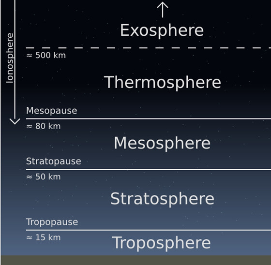
DIFFERENT LAYERS OF THE ATMOSPHERE
Atmospheric Pressure
The atmosphere is held in contact with the earth's surface by the force of gravity, which produces a pressure within the atmosphere.
Gravitational effects decrease with increasing distances from the earth's centre, and this being so, atmospheric pressure decreases steadily with increases of height above the earth's surface.
The units in which atmospheric pressure used in aircrafts are expressed in: pounds per square inch (psi), inches of mercury (in Hg) and millibars (mb).
The steady fall in atmospheric pressure has a dominating effect on the density of the air, which changes in direct proportion to changes of pressure

DIFFERENT UNITS OF PRESSURE
Atmospheric temperature
Another important factor affecting the atmosphere is its temperature. The air in contact with the earth is heated by conduction and radiation, and as a result its density decreases as the air starts rising.
In doing so, the pressure drop allows the air to expand, and this in turn causes a fall in temperature from a known sea-level value.
It falls steadily with increasing height up to the tropopause. and the rate at which it falls is termed the lapse rate (from the Latin lapsus. meaning slip).
In the stratosphere the temperature at first remains constant at some reduced value, then increases again to a maximum.
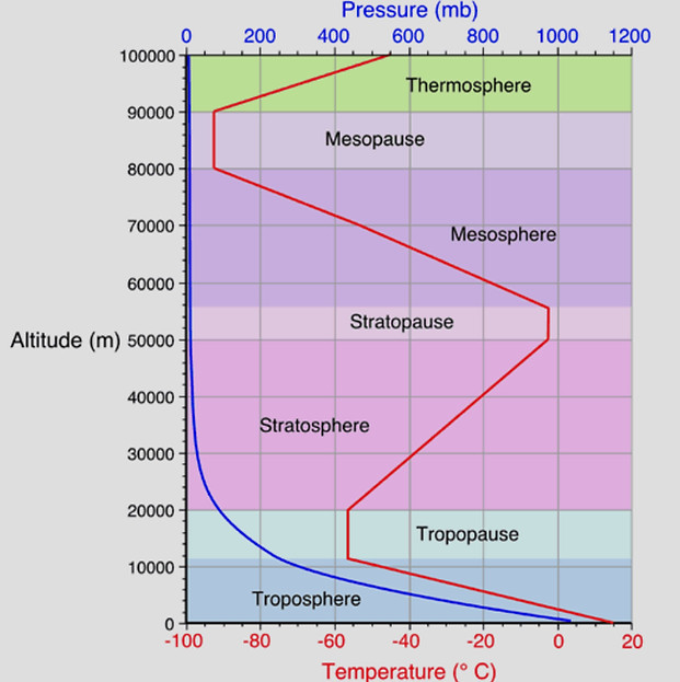
TEMPERATURE AND PRESSURE VARIATION WITH ALTUTUDE
International Standard Atmosphere (ISA)
In order to obtain indications of airspeed, altitude and vertical speed, it is of course necessary to know the relationship between the pressure, temperature and density variables, and altitude. If such indications are to be presented with absolute accuracy, direct measurements of the three variables would have to be taken at all altitudes and fed into the appropriate instruments as correction factors.
Such measurements, while not impossible, would, however, demand some rather complicated sensor mechanisms. It has therefore always been the practice to base all measurements and calculations on what is termed a standard atmosphere, or one in which the values of pressure, temperature and density at different altitudes are assumed to be constant. These assumptions have in turn been based on established meteorological and physical observations, theories and measurements, and so the standard atmosphere is accepted internationally.
The assumptions are:
(i) the atmospheric pressure at mean sea-level is equal to 14.7 psi, 1013.25 mb, or 29.921 in Hg;
(ii) the temperature at mean sea-level is 15°C (59°F);
(iii) the air temperature decreases by 1.98°C (3.556°F) for every 1000 ft increase in altitude (lapse rate) from 15°C at mean sea-level to -56.5°C (-69.7°F) at 36 090 ft. Above this altitude the temperature is assumed to remain constant at - 56.5°C.
It is from the above mean sea-level values that all other corresponding values have been calculated and presented in what is termed the International Standard Atmosphere (ISA).
Pitot and Static systems
Aircraft are subjected to two kinds of pressure static pressure and pitot pressure
Static pressure
When an aircraft at rest on the ground in still air is subject to normal atmospheric pressure or ambient pressure is known as static pressure. It is sensed through a set of small holes situated at a point on the aircraft unaffected by turbulence. This sensing point is known as the static source. It is typically on the side of the fuselage or on the side of a tube projecting into the airstream.
Pitot Pressure
An aircraft in flight, not only experiences static pressure at its flight level, but experiences an additional pressure on the leading edges due to the resistance of the air to the aircraft’s movement, which is know as dynamic pressure
The value of the dynamic pressure depends on the speed of the aircraft through the air and on the density of the air. The leading edges, therefore, encounter a total pressure consisting of static plus dynamic pressures. This total pressure is also known as pitot pressure.
Basic Pitot Static System
The basic form of pitot static system consists of a
-
Pitot-Static Probe
-
Primary Air Data Instruments (airspeed indicator, altimeter and vertical speed indicator)
-
Pipelines and Drains
The Pitot static probe is used to sense the total, or pitot pressure and the static pressure. The probe can be of a combined type with both pitot and static pressure measure by a common probe or can be different units. Pitot probe also have heater to prevent icing.
The primary instruments are
-
Airspeed Indicator which indicate the speed of the aircraft, which is proportional to the difference between pitot pressure and static pressure. Hence both pitot and static pressure are fed to the Airspeed Indicator.
-
Altitude Indicator which indicate the altitude or height about the sea level, which is directly proportional the static pressure.
-
Vertical Speed Indicator which indicate the rate of climb or descent, which is proportional to the difference between static pressure, and a 'case' pressure, produced by a calibrated metering unit.
The displacements are, in turn, transmitted to an indicating element via an appropriate magnifying system.
The systems are connected to each other via pipelines and drains. The function of the drains are to trap the moisture or water content in the system.
The complexity of an air data system depends primarily upon the type and size of aircraft, the number of locations at which primary air data are to be displayed, the types of instrument installed, and the number of other systems requiring air data inputs.
Modern Aircraft consist of Air Data Computers (ADC) which convert the pitot and static pressure to electronic signals with the help of transducers and display the altitude, airspeed and vertical speed on the electronic displays.
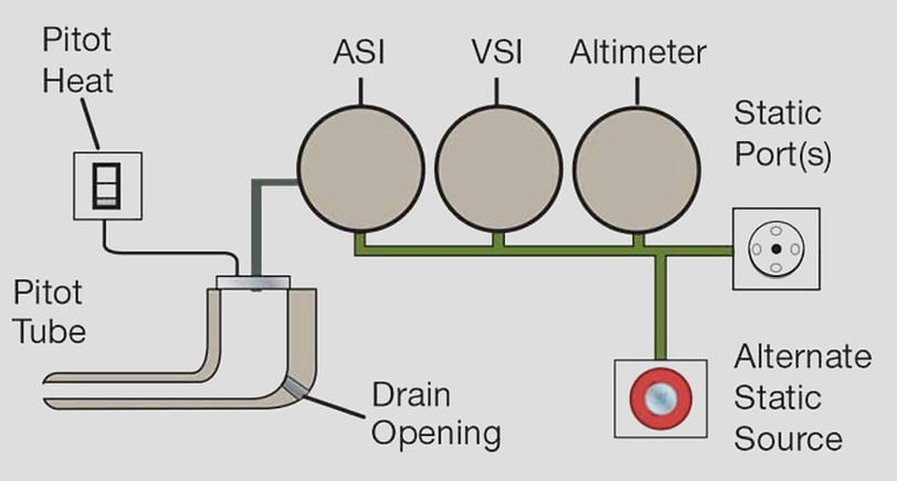
BASIC PITOT STATIC SYSTEM
Pitot Static Tube
The pitot pressure, is sensed by a forward-facing, open-ended tube called a pitot tube, or pitot head, it is usually mounted beneath one wing, or on the side of the forward fuselage, clear of any turbulent airflow.
An electrical heating element is fitted within the tube to prevent the formation of ice, drain holes are provided in the bottom of the tube to allow water to escape.
The static source is duplicated on either side of the rear fuselage. This is to compensate for false readings that would occur if the aircraft were side-slipping or in a crosswind.
The static source consists of a number of small holes in the side of the pitot head, connected to an annular chamber surrounding the pitot tube. This chamber is connected to the static system, which conveys static pressure to the pilot's instruments. A separate pipe connects the pitot tube to the pitot system.

PITIOT PROBE
Position or Pressure Error
Airspeed indicator and altitude indicators are affected by the disturbance to the airflow, vertical speed indicator remains unaffected. Therefore it is important to design a probe which will not cause any disturbance to the airflow over it ; and the other, to find a suitable location on an aircraft where the probe will not be affected by air turbances due to the aircraft itself.
These effects of such disturbances are greatest on the static-pressure measuring section of a pitot-static system giving rise to a pressure or position error (PE) which is defined as the amount by which the local static pressure at a given point in the flow field differs from the free-stream static pressure. As a result of PE, an altimeter and an airspeed indicator can develop positive or negative errors.
A long and small-diameter probe is an ideal one from an aerodynamic point of view, but it may present certain practical difficulties; its stiffness may not be sufficient to prevent vibration at high speed; and it may also be difficult to accommodate the high power heater elements required for anti-icing. Thus, in establishing the ultimate relative dimensions of a probe, a certain amount of compromise must be accepted.
When a probe is at some angle of attack to the airflow, it causes air to flow into the static orifices which creates a pressure above that of the prevailing static pressure, and a corresponding error in static pressure measurement.
The pressures developed at varying angles of attack depend on the axial location of the orifices along the casing, their positions around the circumference, their size, and whether the orifices are in the form of holes or slots.
To reduce PE many types of aircraft by using a pressure head incorporating a pitot tube only, and a static vent in the side of the fuselage. Two static vent are positioned on the opposite side of the fuselage and the two are interconnected for transmission of static pressure to the instruments so that errors produced by yawing are largely eliminated.
Other methods are to employ aerodynamically- compensated pitot-static probes, i.e. probes which are so contoured as to create a local pressure field which is equal and opposite to that of the aircraft, so that the resultant PE is close to zero and more commonly adopted utilize correction devices within separate transducers.
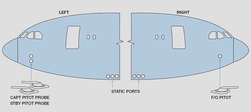
LOCATION OF PITOT PROBE AND STATIC PORTS IN MODERN AICRAFT
Alternate static source
To safeguard against failure of pitot-static pressure source, a standby system may be installed in aircraft employing pitot-static probes whereby static atmospheric pressure and/or pitot pressure from alternate sources can be selected and connected into the primary system.
The required pressure is selected by means of selector valves connected between the appropriate pressure sources and the flight instruments, and located in the cockpit within easy reach of the flight crew.

ALTERNATE STATIC PORT
Pitot Drains and Pipelines
In order for a pitot-static system to operate effectively under all flight conditions, provision must also be made for the elimination of water that may enter the system as a result of condensation, rain, snow, etc., thus reducing the probability of 'slugs' of water blocking the lines.
Such provision takes the form of drain holes in probes, drain traps and drain valves in the system pipelines.
Drain holes are drilled in probe pitot tubes and casings, and are of such a diameter that they do not introduce errors in instrument indications.
Drain traps are designed to have a capacity sufficient to allow for the accumulation of the maximum amount of water that could enter the system between servicing periods.
The drain valves are of the self-closing type so that they cannot be inadvertently left in the open position after drainage of accumulated water.
Pitot and static pressures are transmitted through seamless and corrosion-resistant metal (light alloy and/or tungum) pipelines and flexible pipes, the latter being used for the connection of components mounted on anti-vibration mountings.
Identification of the pipelines is given by conventional colour- coded tapes spaced at frequent intervals along the lines. In addition to this method, the lines in some aircraft may also be of different diameters.
Malfunctions
In order to have correct and reliable indications from the various air data instruments can the pitot and static sources should be kept clear of any blockages and the pitot/static system within the aircraft must remains undamaged and pressure-tight.
Blockage of the pitot or static source may occur due to icing, insects, dirt or dust. It is also not unknown for aircraft painters to forget to remove masking tape from the perforated discs that form the static vents on the fuselage sides.
Blockage of the static sources will cause the altimeter reading to remain constant regardless of changing aircraft altitude, the vertical speed indicator will not indicate rate of change of height and the airspeed indicator will be dangerously inaccurate.
Blockage of the pitot source will not affect the altimeter or vertical speed indicator, but it will render the airspeed indicator useless and the mach meter grossly inaccurate.
Leakage in the piping of the pitot/static system will also seriously affect the accuracy and usefulness of the air data instruments. Loss of pitot pressure due to leakage in the pitot pressure system will cause the airspeed indicator to underread.
Leakage in the static pressure system within the cabin of a pressurised aircraft is a serious problem, since the altimeter will register an altitude equivalent to cabin altitude, which will almost certainly be much lower than aircraft altitude. The vertical speed indicator will not function at all and the airspeed indicator will be inaccurate.
In unpressurised aircraft the effect of a static system leak is less serious, since internal pressure is much the same as external. However, it may change at a slightly slower rate when the aircraft is climbing or descending and this would clearly affect the accuracy of the pressure instruments during height changes.
Altimeter
The altimeter is a simple, reliable, pressure gauge calibrated to indicate height. The pressure at a point depends on the weight of the column of air which extends vertically upwards from the point to the outer limit of the atmosphere.
The higher an aircraft is flying, the shorter is the column of air above it and consequently the lower is the atmospheric pressure at the aircraft.
In other words, the greater the height, the lower the pressure, and by measuring the pressure the altimeter measures height.
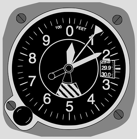
SIMPLE ALTIMETER DISPLAY
Altimeter Construction
The pressure-sensing element for the altimeter is an evacuated metal capsule, which is mounted in a sealed casing, case casing is connected to the static source. Since the capsule is evacuated so there is approximately zero pressure inside the capsule, and assuming the instrument is at sea level, approximately 14.7 lbf/in2 on the outside of the capsule.
The capsule will tend to collapse due to the pressure acting on it, this, is prevented by a strong leaf spring fitted so that one side is attached to the top of the capsule and the other side to the instrument baseplate. The spring always tends to open outwards, and a state of equilibrium is obtained when the pressure is balanced by the spring tension.
As the height of the aircraft decreases the static pressure increases and will cause the capsule to be compressed against the restraining force of the leaf spring, and as the height of the aircraft increases the static pressure decreases which allows the leaf spring to expand the capsule. The spring force ensures that the extent of compression or expansion is proportional to the static pressure being measured. The resulting expansion and contraction of the capsule, which is extremely small, is transformed into rotary motion of the pointer by means of a magnifying lever system and a very finely-linked chain, which is temperature compensated.
The pressure altimeter is calibrated to give a linear presentation of the non-linear atmospheric distribution. This is achieved by the use of a variable magnification lever system and the dynamic design of the capsules.
The setting of the height-indicating pointer can be adjusted by means of the pointer setting knob. The purpose of this is to allow the pilot to set the altimeter so that it displays height above a chosen datum.
For example, if the pointer is set to read zero with the aircraft on the airfield the altimeter will thereafter indicate height above the airfield. Alternatively if, when the aircraft is on the airfield, the pointer is set to read height above mean sea level it will thereafter show height above mean sea level. In both these examples the surface pressure is assumed to remain constant.
The pressure altimeter is calibrated to read height in feet above the ISA mean sea level pressure of 1013.25 hPa. Some altimeters of US manufacture use inches of mercury (in Hg) as the unit of calibration and the equivalent of 1013.25 hPa is 29.92 in Hg. To convert inches Hg to hPa it is necessary to multiply by 33.8639. Conversely, to convert hPa to inches Hg it is necessary to multiply by 0.02953.

SIMPLE ALTIMETER CONSTRUCTION
Sensitive Altimeter
The simple altimeter is rarely used in aircraft because it lacks sensitivity, furthermore the altitude scale is compressed and causes confusion. More accurate height measurement is achieved with the sensitive altimeter.
The principle of operation of the sensitive altimeter is essentially the same as that of the simple altimeter. Sensitivity of response to static pressure changes is improved by incorporating two or three aneroid capsules connected in series with each other.
A bank of two or three capsules transmits altitude changes via a rocking shaft to drive three pointers. These are geared 100:10:1, the smallest indicating 100 000 feet per revolution, the next 10 000 feet per revolution and the largest 1000 feet per revolution.
As the altitude of the aircraft increases the air temperature will fall. The altimeter is calibrated to be accurate when operating at a sea level air temperature of +15°C (ISA mean sea level temperature) and without compensation it will become increasingly inaccurate as instrument temperature deviates from that datum value.
In the sensitive altimeter, temperature compensation is affected by a bimetallic strip inserted between the aneroid capsules and the transmission shaft.

SENSITIVE ALTIMETER CONSTRUCTION
Servo-Assisted Altimeter
In the simple and sensitive altimeter the movement of the aneroid capsule directly moves the altimeter pointer.
At high altitude the change in pressure corresponding to a given change in height is much smaller than at low altitude, hence for a given height change, capsule movement at high altitude is relatively small, and frictional resistance in the linkage of an unassisted altimeter causes correspondingly greater errors and more lag.
In the servo-assisted altimeter the small movements of the capsules are detected by a very sensitive electromagnetic pick-off. When the capsules expand or contract their movement causes an electromagnetic transducer to transmit an electrical signal to a motor, which drives the altimeter’s single pointer and its height counters.
With servo-assistance, the requisite power is available to overcome the frictional resistance with consequently enhanced instrument accuracy. This servo-assistance not only gives the altimeter an increased operating range but also improves the instrument accuracy, particularly at high levels.

SERVO ASSISTED ALTIMETER CONSTRUCTION
AC is fed to the middle leg of the E bar, setting up alternating magnetic fields in the outer legs ‘A’ and ‘B’. The coils on these two legs are wound 180° out of phase. The exciter therefore induces a current in each leg, but since these are 180° out of phase and of equal strength, they cancel each other out when the I bar is equidistant from the legs of the E bar (that is when no pressure change acts on the capsules).
With a change of pressure the capsules expand or contract, moving the I bar on its pivot, closing the gap between the I Bar and E Bar at one end and opening it at the other.
This causes an imbalance of magnetic fields and therefore of the currents induced in the ‘A’ and ‘B’ coils. The imbalance causes an error signal which is passed to the amplifier, where it is amplified and rectified, and thence to the servo motor.
The servo motor drives the counter-pointer system of the altimeter and at the same time, via a cam drive, re-aligns the E Bar with the I Bar. Once realigned, the error signal ceases and the altimeter indicates the correct height.
In this system the only work required of the capsules is to move the I Bar, eliminating the effects of friction and manufacturing imperfections in the gearing of a conventional altimeter.
This type of altimeter is sensitive to very small pressure changes and therefore more accurate than the sensitive altimeter, particularly at high altitudes where pressure changes (per unit height increment) are very small. The lag experienced in other types of altimeter with rapid changes of height is greatly reduced.
When the barometric-pressure setting knob is rotated, the pressure counters are turned and the lever of the setting mechanism moves the worm-gear shaft laterally. This movement of the shaft rotates the cam mechanism, causing relative displacement between the E-bar and I-bar.
An error signal is therefore produced which, after amplification and phase detection, drives the servo motor and gear mechanisms in a sequence similar to that resulting from a normal altitude change, until the null position of the E-bar is reached.
Height, Altitude and Elevation
Before understanding the datum setting it is very important to understand certain terms
Height
The vertical distance of a level, point or object considered as a point, measured from a specified datum.
Elevation
The vertical distance of a fixed (non-moving) point or object measured from mean sea level (MSL).
Altitude
The vertical distance of a moveable object measured from mean sea level (MSL).
Flight level
The Distance measure when standard pressure if set on a altimeter. Which can be different from the mean sea level (MSL)

HEIGHT, ALTITUDE AND ELEVATION
Subscale Settings or Datum
The setting of altimeters to the barometric pressures prevailing at various flight levels and airfields is part of flight operating techniques, and is essential for maintaining adequate separation between aircraft, and terrain clearance during take-off and landing.
In order to make the settings a pilot is dependent on observed meteorological data which are requested and transmitted from ground control centres. The requests and transmissions are adopted universally and form part of the ICAO 'Q' code of communication.
Three code letter groups are normally used in connection with altimeter settings, and are defined as follows:
QFE
This is aerodrome level pressure, which when set on the subscale, will cause the altimeter of an aircraft on the ground to read zero, assuming there is no instrument error.
In flight, with QFE set, the altimeter will indicate height above the aerodrome QFE reference datum, provided ISA conditions exist between aerodrome level and the aircraft and there are no other altimeter errors. This is called as absolute altitude.
In practice, QFE is used mainly for circuit-flying and gives a good indication of height above the aerodrome, any errors involved being only small.
QNH
If mean sea level pressure is set on the subscale the altimeter will indicate height above mean sea level. Thus, when the aircraft is on the airfield the altimeter will indicate airfield elevation above mean sea level. The distance indicated is called as true altitude.
QNE
Setting the standard sea-level pressure of 1,013.25 mbar (29.92 in Hg) to make the altimeter will indicate pressure altitude, that is the altitude above this pressure datum. This setting is used for aircraft flying Flight Levels (FL). It is also called as Standard Altimeter Setting (SAS) and the altitude indicated is transition altitude.
Density Altitude
Density altitude can be defined as the altitude in the standard atmosphere at which the prevailing density would occur, or alternatively, as the altitude in the standard atmosphere corresponding to the prevailing pressure and temperature. It is a convenient parameter in respect of engine performance figures.
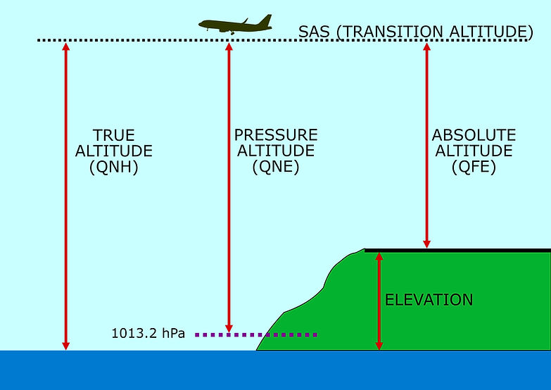
TRUE ALTITUDE, PRESSURE ALTITUDE AND PRESSURE ALTITUDE
Altimeter errors
Pressure altimeters are prone to a number of errors, which are as follows
Time Lag error
There is inevitably a delay between an atmospheric pressure change and the response of the aneroid capsules, with the result that the movement of the instrument pointer lags behind a change in altitude. The magnitude of the error depends upon the rate of change of altitude and is clearly unacceptable. In sensitive altimeters it is often reduced by means of a vibrator, or knocking, mechanism, which has the same effect as tapping a barometer to make the pointer move after a small pressure change. In servo-assisted altimeters lag error is virtually eliminated by the reduction of mechanical resistance.
Blockage of static source
If the static source becomes blocked the altimeter will cease to indicate changes of static pressure, and therefore of altitude. The effect will be that the altimeter will continue to indicate the reading at which the blockage occurred.
Should the static line fracture in a pressurized aircraft, the altimeter will show the (lower) cabin altitude rather than aircraft altitude
A fracture in the static line within an unpressurized aircraft will normally result in the altimeter over-reading, due to the pressure in the cabin being lower than ambient due to aerodynamic suction.
If the aircraft is CLIMBING then the altimeter will UNDER-READ.
If the aircraft is DESCENDING then the altimeter will OVER-READ.
Instrument error (IE)
As with any mechanical device, the pressure altimeter is manufactured with small tolerances in its moving parts and these give rise to small inaccuracies in its performance. They are usually insignificant, but in some cases a correction table may be supplied with the instrument.
Position error (PE)
The static source is positioned at a point on the airframe where disturbance to the airflow is minimal, so that the static pressure measured is as close as possible to the undisturbed ambient static pressure. However, there is usually some small error due to the positioning of the static source. Use of the alternate static source may also cause pressure error, since its siting is different to that of the normal source and thus subject to different effects during manoeuvring. The PE for an aircraft type is determined during its initial flight tests and is supplied in tabular or graphical format so that the pilot may make the appropriate corrections. In servo-assisted altimeters the correction is usually incorporated into the transducer system.
Corrections to be applied to the altimeter reading for position error may be listed in the Aircraft Operating Manual (AOM). These are usually small and take account of the effects of aircraft speed, weight, attitude and configuration, since all of these factors have some effect on airflow over the static source. Corrections are also usually given for both the normal and alternate static source, since position error may not be the same for both.
The correction is applied as indicated in the AOM tables. For example, suppose the tables state that the correction to be applied with flaps at the landing setting of 45° is +25 ft, then 25 ft must be added to the altimeter reading.
Pressure error
Also known as barometric error and subscale-setting error, this occurs when the actual datum pressure differs from that selected on the subscale setting of the altimeter.
Temperature error
The altimeter is calibrated to assume a Standard Atmosphere temperature lapse rate of 1.98°C per 1000 ft. Actual temperatures at any given altitude usually differ from this assumption and the altimeter will be in error. In cold air the density is greater than in warm air and a given pressure will occur at a lower altitude than in warmer air.
Consequently, the altimeter will overread and, with QNH set, the aircraft will be lower than indicated, with the error increasing from zero at msl to a significant amount at altitude. The AOM contains a table of corrections for this situation. These corrections must be added to published or calculated heights/altitudes when temperature is less than ISA.
A `rule of thumb' calculation of altitude temperature error is that the error will be approximately 4% of indicated altitude for every 10°C temperature deviation from ISA.
Airspeed Indicator (ASI)
The measurement and indication of airspeed of an aircraft is essential for the pilot, because many critical factors depend upon the speed of flight.
For example, the pilot needs to know when the aircraft is moving fast enough for take-off, when it is flying close to the stalling speed, when it has accelerated to the speed at which landing gear and flaps must be raised and when it is approaching the maximum safe flying speed, to name but a few. This critical information is provided by the airspeed indicator (ASI).
A simple ASI typically uses a single pointer that moves around a scale calibrated in knots. More complex instruments may be used in high-speed aircraft, incorporating an angle-of-attack indicator or a mach meter.
The aircraft's speed relative to the surrounding air is proportional to the dynamic pressure that results from the air being brought to rest on forward facing parts of the airframe.
The airspeed indicator measures dynamic pressure and converts this to an indication of airspeed.
Since pitot pressure (P), as measured in the pitot tube, is a combination of dynamic pressure (D) and static pressure (S), i.e. P = D + S.
Therefore dynamic pressure is pitot pressure less static pressure, i.e. D = P - S.
Thus, the function of the ASI is to remove the static pressure element of pitot pressure and use the resulting dynamic pressure to move a pointer around a graduated scale.

AIRSPEED INDICATOR (ASI) DISPLAY
Construction of Airspeed Indicator (ASI)
Since dynamic pressure cannot be directly measured; it must be obtained from the difference between pitot and static pressure.
It is therefore necessary to construct a device in which static pressure is subtracted from pitot (total) pressure in order to isolate dynamic pressure.
The instrument comprises of hermetically-sealed instrument case connected to the static source and containing a capsule supplied with pitot pressure. The capsule capable of expansion and contraction.
Pitot pressure fed inside the tube is dynamic pressure plus static pressure (D+ S), hence static pressure is present on both the inside and the outside of the metal walls of the capsule, so cancels it each other. Therefore the pressure differential between the inside and outside of the capsule is ((D + S) - S) which is Dynamic. Therefore the capsule will expand or contract proportional to the changes in dynamic pressure. Hence Indicate the airspeed of the aircraft.
The faster the aircraft flies through the atmosphere, the greater will be the resultant dynamic pressure and the capsule will expand.

AIRSPEED INDICATOR CONSTRUCTION
AGER: Airspeed Indicator Reading
The speed of the aircraft not only depends on the dynamic pressure but also depends on the density of air. This density varies with temperature and pressure and therefore with altitude.
The ASI is calibrated to read true airspeed for the air density of 1225 grams per cubic metre which would be produced by the ISA MSL pressure of 1013.25 hPa and temperature + 15°C (dry air conditions).
No allowance is made in the calibration for the change in density which occurs with change of altitude. As the ASI is only calibrated at MSL, and ISA conditions, flight at any other height will cause errors.
Therefore in order to display the true airspeed the measure airspeed has to be compensated for various types of errors. This had given rise to a number of air speed terminologies
Indicated airspeed (IAS)
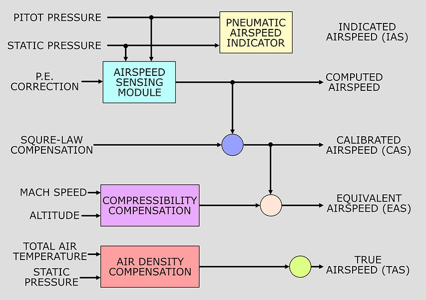
Indicated airspeed (IAS) is the speed indicated by the simple airspeed indicator reading (ASIR) corrected for errors due to manufacturing tolerances in the instrument (instrument error), but not corrected for static pressure errors occurring at the static source (pressure error).
Calibrated airspeed (CAS)
Calibrated Airspeed (CAS) is the airspeed obtained when the corrections for instrument error (IEC) and pressure error (PEC) have been applied to IAS. These correction values are usually found in the Aircraft Operating Manual and may be reproduced on a reference card kept in the cockpit.
CAS = IAS + PEC
Calibrated airspeed used to be referred to as rectified airspeed (RAS).
Equivalent Airspeed (EAS)
Because air is a compressible fluid it tends to become compressed as it is brought to rest. At low to medium airspeeds the effect of compression is negligible, but above about 300 knots TAS the compression in the pitot tube is sufficient to cause the airspeed indicator to overread significantly.
The greater the airspeed above this threshold, the greater the error due to compression. The effect is also increasingly noticeable at high altitude, where the lower density air is more easily compressed. The error produced by this effect is known as compressibility error.
Compressibility error correction (CEC) can be calculated and when applied to the calibrated airspeed the result is known as equivalent airspeed (EAS).
EAS = CAS + CEC.
True Airspeed (TAS)
The airspeed indicator only indicates true airspeed (TAS) when ISA mean sea level conditions prevail; any change of air density from those conditions will cause the indicated airspeed to differ from true airspeed. The greater the altitude, the lower will be air density and therefore IAS (and consequently EAS) will be progressively lower than TAS.
The error due to the difference in density from ISA msl density can be calculated.
When this density error correction (DEC) is applied to EAS the result is the aircraft's true airspeed (TAS).
TAS = EAS + DEC.
The compressibility error and density error corrections are embodied in the circular slide rule (navigation computer), from which TAS can be found using CAS and the appropriate altitude, speed and temperature settings.
TYPES OF AIRSPEED
Square law compensation
Airspeed indicators measure a differential pressure which varies with the square of the airspeed, the deflections of the capsules responded linearly to the pressure, If also the capsule were coupled to the pointer mechanism so that its deflections were directly magnified and nonlinear.
Thus, at low airspeeds the amount of expansion for a given increase in speed will be small, whereas at higher airspeeds the amount of expansion will be relatively large for the same speed increase.This is known as square law expansion and, transmitted to the instrument pointer, will require an expanding scale on the face of the ASI.
Such a scale makes accurate interpretation of airspeed difficult at low speeds and limits the upper speed range that can be displayed.

AIRSPEED INDICATOR NON LINEAR SCALE
The linearity of the indication can be controlled by either the capsule characteristic, or the movement of the coupling element conveying capsule deflections to the pointer.
Of the two methods the latter is the more practical because means of adjustment can be incorporated to overcome the effects of capsule 'drift' plus other mechanical irregularities as determined during calibration.
The principle of a commonly used version of the foregoing method is one in which the length of a lever is altered as progressive deflections of the capsule take place, causing the mechanism, and pointer movement, to be increased for small deflections and decreased for large deflections.
In other words, it is a principle of variable magnification.
Another type of square-law compensating device consists of a special ranging or 'tuning' spring which bears against the capsule and applies a controlled retarding force to capsule expansion. The retarding force is governed by sets of ranging screws which are pre-adjusted to contact the spring at appropriate points as it is lifted by the expanding capsule.
As speed and differential pressure increase, the spring rate increases and its effective length is shortened; thus linearity is obtained directly at the capsule and eliminates the need for a variable magnifying lever system.
In some types of servo-operated indicators, a specially profiled cam provides square-law compensation.

SQUARE LAW COMPENSATION
Airspeed Indicator (ASI) speed limits and colour markings
The ASI scale is often marked with coloured arcs and radial lines.
VNO = The maximum normal operating limit speed (i.e. flaps and landing gear retracted).
VNE = The Never Exceed speed, beyond which structural damage may occur. It is indicated on the ASI presentation by a red radial line.
VSO = The stall speed or the minimum steady flight speed in the landing configuration(flaps and landing gear fully extended).
VS1 = The stall speed or the minimum steady flight speed in a specified configuration.
VFE = The maximum Flap Extension speed
VYSE = best rate of climb speed with one engine failed
Vmo/Mmo
Some ASIs incorporate a red and white striped pointer showing the maximum allowable airspeed (Vmo) which is often the mach-limiting airspeed, at which the airflow over parts of the airframe will be approaching the critical mach number (Mcrit) for the aircraft. The pointer is actuated by a static pressure capsule and specially calibrated mechanism. This allows the Vmo pointer reading to increase progressively up to about 25 000 ft, as the air becomes less dense. Above this altitude the Vmo pointer reading is progressively decreased, since Mcrit will be reached at progressively lower values of indicated airspeed.
VLO = The maximum Landing Gear Operation speed (up or down).
VLE = The maximum speed Landing Gear Extended speed
The colour marking are as follows
The White Arc denotes the flap operating range, from stall at maximum AUW in the landing configuration (full flap, landing gear down, wings level, power-off) up to VFE (maximum flaps extended speed).
The Green Arc denotes the normal operating speed range, from stall speed at maximum all-up weight (flaps up, wings level) up to VNO (‘normal operating limit speed’ or ‘maximum structural cruising speed’) which should not be exceeded except in smooth air. Operations at IASs in the green arc should be safe in all conditions, including turbulence.
The Yellow Arc denotes the caution range, which extends from VNO (normal operating limit speed) up to VNE (the never exceed speed). The aircraft should be operated at IASs in the caution range only in smooth air.
A Red Radial Line denotes VNE, the never exceed speed.
Optionally for piston engined light twins:
A blue radial line denotes the best rate of climb speed for one engine out, maximum weight, at mean sea level (VYSE).

AIRSPEED INDICATOR COLOUR AND SPEED LIMIT MARKINGS
Airspeed Indicators (ASI) errors
The Airspeed indicator (ASI) are subjected to a number of errors are which are as follows
Instrument Error
This is effectively the same as for the pressure altimeter. It is the error between the airspeed that the ASI should indicate and that which it actually does, due to manufacturing tolerances and friction within the instrument.
Position or Pressure Error
This is the error caused by pressure fluctuations at the static source. These may be due to the position of the static source, hence the term position error. The error can be determined over the speed range of the aircraft and recorded on a correction card. Pressure error may also occur when the aircraft is at an unusual attitude or when flaps or landing gear are extended, in which case it is known as manoeuvring error. These data are normally found in the AOM.
Compressibility Error
At true airspeeds above about 300 knots the air brought to rest in the pitot tube is compressed to a pressure greater than dynamic pressure, causing the ASI to overread. The effect increases with altitude, since less dense air is more readily compressed. The compressibility error correction can be found using the circular slide rule (navigation computer).
Blocked Pitot Tube
A blocked pitot tube will mean that the pressure in the pitot system will be unaffected by changes in airspeed. In level flight the ASI will indicate a false airspeed, dependent upon the pressure locked in the system, and will not indicate changes in airspeed. In the climb the decreasing static pressure will cause the ASI capsule to expand and the instrument will falsely indicate an increasing airspeed. In the descent the reverse will be the case.
Blocked Static Source
A blocked static source will cause the ASI to underread as the aircraft climbs above the altitude at which the blockage occurred, since the pressure trapped in the instrument case will be progressively greater than ambient static pressure. In the descent the reverse will happen and a hazardous condition arises, since the progressively overreading ASI may cause the pilot to reduce power and airspeed may fall below stalling speed. A blockage to the static source during level flight will not be readily apparent, since the ASI indication will not change.
A useful mnemonic for examinations is PUDSOD, which stands for
‘Pitot Blocked: – Under-reads in Descent
Static Blocked: – Over-reads in Descent’
Mach Meter
The speed at which sound travels through the air is known as the speed of sound, or sonic speed. This speed varies with air temperature and therefore with location. The speed of sound at any specific location is known as the local speed of sound (LSS).
Aircraft that are not designed to fly at supersonic speeds usually suffer both control and structural problems when the airflow over the air- frame, particularly over the wings, approaches the LSS. Consequently it is essential that pilots of such aircraft be aware of the aircraft's speed relative to the LSS. This is especially important at high altitude, since the speed of sound decreases with temperature, and air temperature decreases with altitude in a normal atmosphere.
Hence, the greater the altitude, the lower the LSS.
The aircraft's speed relative to the LSS is measured against a scale in which the LSS is assigned a value of 1. The limiting speed above which control problems may be encountered is known as the critical mach speed and is assigned a value known as the critical mach number (Mcrit).
Supposing that, for a particular aircraft, this speed happens to be 70% of the LSS, then the critical mach number would be 0.7.
The mach number (M) is the ratio of the aircraft's true airspeed (TAS) to the LSS.
Thus, if an aircraft is flying at a TAS of 385 knots at an altitude where the LSS is 550 knots, the aircraft's mach number is 385/550 = 0.7.
Clearly, if the aircraft were flying at a TAS of 550 knots in these conditions its mach number would be 1.0 and it would be flying at sonic speed.

MACHMETER DISPLAY
The speed of sound in air is entirely dependent upon the air temperature. The lower the air temperature, the lower the LSS, therefore LSS decreases with increasing altitude in a normal atmosphere. The LSS can be calculated using the formula:
LSS = 38.94√TK
where TK is the local air temperature in degrees kelvin.
Since mach number is the ratio of TAS to LSS it follows that mach number is also dependent upon local air temperature. At any given true airspeed the aircraft's mach number varies inversely with temperature.
The mach meter is essentially a pressure altimeter and an ASI combined in one instrument. Its purpose is to indicate the aircraft's airspeed relative to the LSS.
We have seen that the LSS decreases with air temperature and, therefore, with altitude in a normal atmosphere.
The mach meter contains an altitude capsule similar to that in the pressure altimeter. Static pressure is supplied to the sealed instrument casing and the aneroid altitude capsule will expand against a light spring as static pressure decreases with increasing altitude. The instrument also contains an airspeed capsule, the inside of which is connected to pitot pressure. As airspeed, and therefore dynamic pressure, increases the airspeed capsule will expand, exactly as in the ASI.
The movement of the altitude and airspeed capsules is transmitted to the mach meter pointer through a system of mechanical links and gears. The pointer rotates against a dial calibrated to show the aircraft speed in terms of mach number.
As a pressure instrument the mach meter cannot measure the ratio of TAS to LSS, but it satisfies the requirement by measuring the ratio of dynamic pressure (pitot - static) to static pressure.
This can be expressed as:
M =(P-S)/S
From the foregoing it follows that an increase in airspeed will raise the mach number, bringing the aircraft's speed closer to the LSS. An increase in altitude will reduce the LSS, also bringing the aircraft's speed closer to the LSS, raising the mach number.
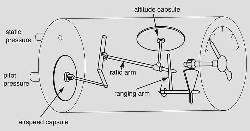
MACHMETER CONSTRUCTION
Mach meter errors
Like the Altimeter and Airspeed Indicator(ASI) the machmeter is also subjected to errors which are as follows
Instrument error
In common with all pressure instruments the manufacturing tolerances inevitably lead to small errors of measurement due to friction and lost motion in the linkages and gearing. These are typically of the order of +0.1M over a range of 0.5M to 1.0M. Instrument error increases slightly with increasing speed and altitude.
Pressure error
The mach meter is more sensitive than the ASI to errors in static pressure measurement, since it uses the ratio of dynamic pressure (P-S) to static pressure, whereas the ASI uses the ratio of pitot pressure to static pressure.
Blockages
Blockage of either pressure source will cause the measured ratio to be incorrect. If the static source is blocked, changes in altitude will not be sensed and the instrument will underread in the climb. If the pitot source becomes blocked the instrument will not respond to speed changes.
Vertical Speed Indicator (VSI)/ Rate of Climb or Descent Indicator
The Vertical Speed Indicator (VSI) displays rate of climb or descent,or the vertical speed in typically feet per minute. The instrument senses rate of change of static by comparing the present static pressure with the static pressure measured 4-6 seconds earlier. This is achieved by a metering unit within the instrument.
The VSI is alternatively known as the rate of climb/descent indicator (RCDI).
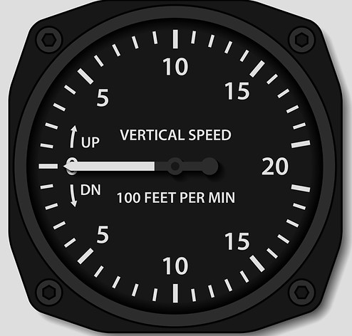
VERTICAL SPEED INDICATOR (VSI) DISPLAY
Static pressure is led directly to the inside of a capsule and also to the inside of the sealed instrument casing via a metering orifice. The capsule is connected to a pointer through linkages and a quadrant and pinion gear.
Whilst the aircraft is in level flight the pressure in the capsule is the same as that in the casing and the pointer is in the horizontal, nine o'clock position indicating zero.
When the aircraft enters a climb, static pressure begins to fall and this is sensed virtually immediately within the capsule. Pressure in the instrument casing is now greater than that in the capsule, since air can only escape at a controlled rate through the restricted orifice of the metering unit. The pressure difference causes the capsule to contract, driving the pointer in a clockwise direction to indicate a rate of climb. The faster the aircraft's rate of climb, the greater will be the pressure difference between capsule and casing and the greater the capsule compression, driving the pointer further around the scale.
During a descent the increasing static pressure will be felt virtually instantly within the capsule, but the pressure in the instrument casing will rise at a slower rate due to the effect of the metering unit. Hence the capsule will expand, against a spring, driving the pointer in an anti-clockwise direction to indicate a rate of descent proportional to the pressure difference, which is in turn proportional to the rate of descent.
When the aircraft levels out at a new altitude the pressure in the instrument casing will equalise with that in the capsule and the pointer will return to zero.
The scale graduation is logarithmic, having greater spacing at lower rates of climb. This is done, to facilitate easy interpretation when small changes of height are being made.
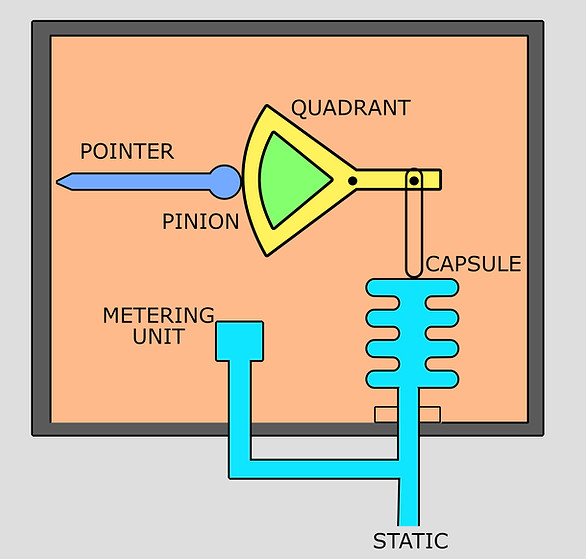
VERTICAL SPEED INDICATOR CONSTRUCTION
Vertical Speed Unit Metering Unit
The restrictor (or choke, or metering unit) is more complicated than a simple hole. The static pressure change is actually hectopascals/min, but the pilot needs to see an indication of feet/ min, whatever the altitude. However, there are more feet to a hectopascal at higher altitudes than lower altitudes, and therefore the rate of pressure change with altitude at different altitudes needs to be compensated for.
This is achieved by a combination of different types of hole (called ‘capillary’ and ‘orifice’).
The pressure difference across a capillary, for a constant rate of climb, increases with increasing altitude and at a constant temperature. Thus, the use of a capillary alone would introduce a positive error in instrument indications at altitudes above sea-level. With an orifice, the effect is exactly the opposite.
The primary reasons for the difference are that the air flow through a capillary is a laminar one while that through an orifice is turbulent; furthermore, the rate of flow through a capillary varies directly as the differential pressure, while that through an orifice varies as the square root of the differential pressure. In combining the two devices we can therefore obtain satisfactory pressure compensation at a given temperature.
The differential pressure across a capillary also depends on the viscosity of the air, and as this is proportional to the absolute temperature, it therefore decreases with decreasing temperature.
The differential pressure across an orifice varies inversely as the temperature, and therefore increases with decreasing temperature. Thus, satisfactory temperature compensation can be obtained by combining the two devices.
The sizes of the orifice and capillary are chosen so that the readings of the indicator will be correct over as wide a range of temperature and altitude conditions as possible.
Instantaneous vertical speed indicator (IVSI)
One of the disadvantage of the basic VSI is that there is an inherent time lag in displaying climb or descent when either is initiated. This is due to the hysteresis of the capsule, which needs a significant pressure differential before it begins to expand or contract. In aircraft of moderate performance this is unimportant, but in higher performance aircraft an instantaneous response to height change is necessary.
This is achieved by using a dashpot accelerometer. The accelerometer comprises two small cylinders or dashpots, containing pistons held in balance by springs and their own mass. The cylinders are connected in the capillary tube leading to the capsule, and are thus open directly to the static pressure source.
When a climb is initiated, inertia due to vertical acceleration force, causes the piston to move down in the cylinder, creating an instantaneous, but temporary, pressure drop in the capsule. The capsule immediately contracts, causing the instrument to indicate immediately the commencement of a climb. Thereafter, the decreasing static pressure due to the climb causes an indicated rate of climb.
When a descent is initiated, inertia causes the dashpot piston to rise in its cylinder, creating a small instantaneous pressure rise in the capsule, sufficient to expand it and indicate the commencement of descent.
A minor disadvantage of the IVSI is that, on entering a turn in level flight, the centrifugal acceleration force is liable to displace the dashpot piston and cause a temporary false indication of climb. Upon exiting the turn the reverse will be the case. The IVSI is also more sensitive to turbulence and is liable to give a fluctuating indication in such conditions. This is usually damped out by the inclusion of a restriction in the static connection to the capsule and the metering unit.
An adjusting screw is provided below the face of the instrument, by which the pointer can be set to read zero. The range of adjustment available is, typically, between +200 ft per minute and +400 ft per minute, depending upon the scale range of the instrument.
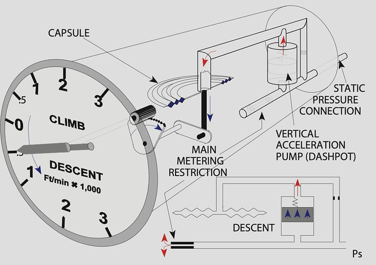
INSTANTANEOUS VERTICAL SPEED INDICATOR (IVSI) CONSTRUCTION
Vertical Speed Indicators Errors
The vertical speed indicator is subjected to the following errors
Instrument error
Manufacturing tolerances lead to small errors in the internal mechanism. When these cause displacement of the pointer from the zero position with the aircraft stationary on the ground it can be corrected with an adjusting screw on the front of the instrument.
Pressure error
Disturbances at the static source may cause the instrument to display an incorrect rate of change of height.
Time Lag
A delay of a few seconds before a rate of change of height is indicated is normal with the basic VSI. The IVSI virtually eliminates lag.
Transonic jump
A transonic shock wave passing over the static source will cause the VSI briefly to give a false indication.
Blockage
Blockage of the static source will render the VSI useless, since it will permanently give a zero indication.
Failure of the instrument will usually result in a fixed indication of zero rate of change of height.
Air Data Computer (ADC)
The pressures for the primary flight instruments is transmitted through a system of pipelines which vary in length and quantity of the pipelines according to the size of the aircraft.
Therefore in order to minimize the 'plumbing' arrangements, the concept of supplying the pressures to a special unit at some centralized location, and then transmitting the air data electrically to wherever required, central air data computers (CADC) were developed.
The computer unit and displays, together with the sensors of the basic data of pitot pressure, static pressure and air temperature, and a power-pack, form the aircraft’s Air Data System (ADS).
The outputs are fed to the aircraft’s Automatic Flight Control System (AFCS), altitude transponder, flight data recorder, navigation computer and more.
The standard ADS instruments show altitude, vertical speed, airspeed and MNo. Additional instruments can display Total Air Temperature (TAT), Static Air Temperature (SAT) and TAS.
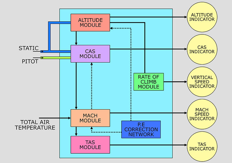
Pressure sensing is accomplished by two pressure transducers, one sensing static pressure within the altitude module, while the other senses both pitot and static pressures within the computed airspeed (CAS) module. The Mach speed module and true airspeed (TAS) module are pure signal-generating devices, which are supplied with altitude and airspeed signal data from the respective modules. Static air temperature data required for TAS computation is sensed by a probe located outside the aircraft at some predetermined position, and is routed through the Mach speed module.
.jpg)
BASIC AIR DATA COMPUTER
Analogue and digital ADCs
There are two types of ADC system Analogue or Digital from the method of assessment and transmission of information used.
Analogue air data computers, which transmit their output data to servo- operated devices. The relationships between TAS, Mach No., temperature, pitot and static pressures can be expressed as mathematical formulae. The ADC resolves these formulae continuously to produce the required outputs from pressure and temperature inputs in the form of shaft rotations or electrical signals.
The Digital system uses digital data (binary data) in its assessment and transmission of information. The Analogue to Digital Converters, at the input side of the ADC, use measurements of pressure, temperature and AOA and change them from the analogue form to digital form for use within the ADC and onward transmission to the flight deck.
The figure shows an airspeed assessment device from an Analogue ADC indicating the inputs of static and pitot pressure. The pressures are joined together mechanically and, using a Pressure Transducer, transmitted forward for use through the rotation of a shaft driven by a 2-phase servomotor which in turn is connected to a CX synchro where angular position can be measured and read off as an airspeed.
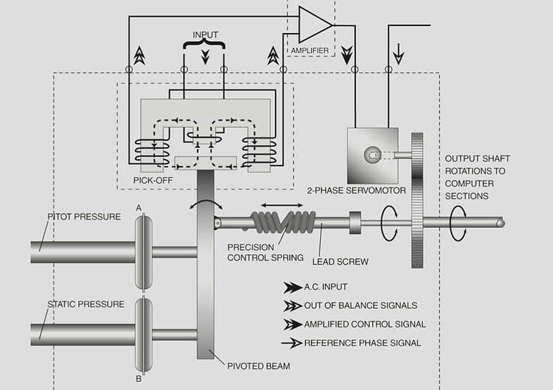
ANALOGUE AIRSPEED AIR DATA COMPUTER
Redundancy
Provision for blockages and / or failure of an ADC is made through change-over cocks that permit an alternative static source to be connected to the computer or by the use of electrical switching that enables the Captain’s instrument to be fed from the First Officer’s ADC and vice versa.
In some aircraft the ADS is designed so that the outputs from each computer are not directed exclusively to instruments on one side of the panel. By mixing the sources of air data to each side, the possibility of an undetected malfunction is reduced.
In the event of total failure of both ADCs due perhaps to loss of power supply, the flight can be continued by reference to the standby instruments.
Failure Warining
A comparison monitor can be incorporated to compare the outputs of the ADCs and to give automatic warning to the pilot of malfunction. With a purely mechanical system, comparison between left-hand and right-hand instruments must be carried out visually. A warning flag will appear on the appropriate ADS instrument if there is loss of valid data or if an internal failure occurs. In addition, a light will illuminate either on the instrument warning panel or on the central warning system indicator.
There is no provision made for the manual input of data into the ADC in the event of any failure, but the Built-in Test Equipment will give prompt indication of any malfunction that might occur. In any ADC there will be three types of BITE process:
Power Up BITE
This functions when power is applied to the ADC on start-up or after a break. A check is made on the Microprocessor, the Memory Store and the Air Data functions.
Continuous BITE
This is an automatic check of all stages of input and output carried out throughout the operation of the ADC about once every second.
Maintenance BITE
This enables maintenance crew to carry out checks on the ground using a Test or Test/History switch (current or post failures).
Temperature measurement probes
The measurement of temperature is an important factor for any aircraft. There are two kinds of temperature which are required
SAT (static air temperature)
This is the temperature the air at the surface of the aircraft would be at if there were no compression effects due to the aircraft's movement. At very low airspeeds these effects are negligible, but for most transport aircraft normal flight speeds are such that the direct measurement of SAT is virtually impossible. SAT is also known as outside air temperature (OAT).
TAT (total air temperature)
Total air temperature is the temperature of the air when it has been brought completely to rest, as in the pitot tube. The ram rise, that is the temperature increase due to compression, can then be subtracted from TAT to give corrected outside air temperature (COAT). The value of ram rise can be calculated for any given mach number, so clearly the air data computer can be programmed to make this correction.
Air Temperature Thermometers
Air temperature thermometers can be divided into 2 basic types: Direct Reading or Remote Reading.
Direct Reading. These work on the principle of differential coefficients of expansion with temperature. Invar is a nickel steel alloy notable for its uniquely low coefficient of thermal expansion. A bimetallic strip is constructed consisting of invar and brass bonded together as shown in Figure 3.1.
When this strip is heated, the brass, having a higher coefficient of expansion than the invar, will expand more than the invar so that the strip curls as shown. How much the strip curls depends on the temperature rise to which the strip is subjected.
The strip is drawn out into a helix, to give greater pointer movement for a given temperature rise, and is incorporated into an instrument with a dial as shown in Figure 3.2.
The thermometer is mounted on the windscreen or fuselage with the tube protruding out into the air stream and the dial visible to the pilot, as shown in Figure 3.3.
Remote Reading. However, the direct reading thermometer is not a workable solution for a larger aircraft. Firstly, a device that penetrates the windscreens would weaken the structure to an unacceptable extent at the pressures associated with higher speeds. Secondly, it is desirable to have the temperature information in an electrical form so that it can be fed to other instruments and systems.
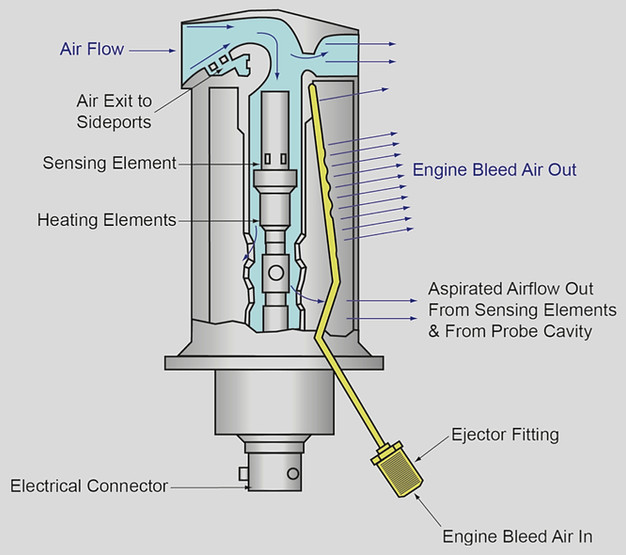
Total Air Temperature Probe
The probe is in the form of a small strut and air intake made of nickel-plated beryllium copper, which provides good thermal conductivity and strength. It is fixed to the fuselage at a point which keeps it away from the aircraft’s boundary layer.
As the air flows through the tube, separation of water particles is achieved by causing the airflow to turn through a right angle before passing round the sensing element. The bleed holes in the intake casing permit boundary air to be drawn off because of the higher pressure inside the intake.
A resistance wire made of pure platinum is used as the sensor. It has a very high thermal conductivity and a rapid response to change. An inbuilt heating element prevents the formation of ice. It is self-compensating – as the temperature rises, so does the heater resistance, reducing the heater current.
The heater can have a small effect on the temperature readings. However, this introduces an error of less than 1°C, which is not significant.
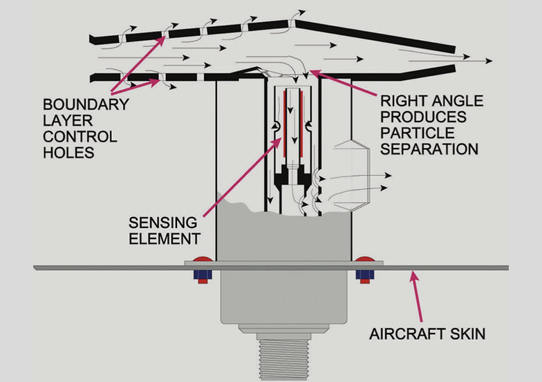
AIR TEPMERATURE PROBE
It is also necessary to measure air temperature on the ground. Modern aircraft do not use full power for take-off in order to avoid unnecessary thermal stress to the engines. The take-off is carried out using the minimum power necessary to ensure safety, but no more. Runway length, weight, altitude and temperature are taken into consideration in the calculation of the required power and it is perfectly normal to carry out a take-off at, say, 93% power.
In order to measure air temperature on the ground an air to air ejector (aspirator) is used, bleed air from either an APU or a running engine creates a negative differential pressure within the casing so that outside air is drawn through it even when the aircraft is stationary in order to prevent the temperature of stagnant, heat-soaked air from within the casing being measured.
The engine bleed air is positive pressure from one of the engine compressor stages. Although it is blowing, not sucking, the flow is arranged such that the rearward movement of the engine bleed air creates a suction effect past the sensing element