
Aircraft Warning Systems
Introduction
The purpose of the Flight Warning System (FWS) is to produce cautions and warnings for the crew to increase their situation awareness and to give them suitable indications of the action necessary to avoid impending danger.
The proliferation of various warning systems in today’s aircraft poses a severe problem in that the crew could be confused by the multiplicity of warnings. It is therefore necessary to install an integrated flight warning system that will prioritize the warnings. By producing warnings relevant to a particular stage of flight and inhibiting other warnings the system enables the crew to respond to the warning posing the most immediate threat to safety.
Levels of Alerts
The alerting and warning system produces the following levels of alerts:
-
Warnings or Level A alerts: These require immediate crew action. Warnings must attract the pilot’s attention in sufficient time for appropriate action to be taken.
-
Cautions or Level B alerts: These require immediate crew alertness and subsequent crew action.
-
Advisories or Level C alerts: These require crew alertness.
Warnings in General
The alerting and warning messages are presented to the crew in visual, aural and sensory (tactile) forms.
Visual
The level of alert is indicated by colours as follows:
-
Warnings are presented in red
-
Cautions are shown in amber or yellow
-
Advisories are any colour except red or green. (On EICAS panels they are also amber)
These visual indications can be presented in two different forms:
-
Electronic Screens: Alerts and warnings appear in coloured text or symbols on various electronic screens (flight, navigation, engine and aircraft system displays).
-
Lights or Flags: Red lights or reflective flags signify warnings and require remedial action if flight is to continue. An amber light or flag is used to indicate that a system or equipment is approaching a limit of normal function and that corrective action is necessary to prevent further deterioration and consequent failure.
Additionally, master warning and caution lights are normally provided and are located near the centre of scan in front of each pilot.

MASTER WARNING AND CAUTION LIGHTS
Aural
An audible warning is mandatory if the pilot is required to assume control. This can be in a variety of forms depending upon the type of aircraft. The alert can be in the form of sounds or synthetic voice messages or a combination of both. For multiple alerts, the warnings are prioritized: Stall, Windshear, GPWS, ACAS.
Warnings
Boeing aircraft produce the following aural warnings:
-
A bell accompanies fire messages
-
A siren accompanies warnings on cabin altitude, configuration and overspeed
-
A wailer accompanies autopilot disconnect
-
Synthetic voice messages for ground proximity, windshear, airborne collision avoidance
Airbus aircraft produce:
-
continuous repetitive chimes (red warnings)
-
cavalry charge (autopilot disconnect)
-
cricket sound (stall warning)
-
synthetic voice (GPWS, TCAS warnings)
Cautions
-
Beepers with various tones or chimes or musical chords are used to caution the crew to potential threats to safety.
Sensory
A vibratory mode on the controls is used to indicate stall approach and demands immediate action to avert loss of control. In some aircraft a stick-pusher provides guidance to prevent a further deterioration of the situation that demanded the vibratory warning.
To rationalize warnings systems, a Master Warning Indicator light is often provided near the centre of scan. In older systems the crew member would then refer to a Master Centralized Warnings Panel (CWP) where warnings were assembled in a rational order and annotated.
In the modern Electronic Flight Instrumentation Systems (EFIS) most of the alerts and warnings appear on appropriate electronic screens together with associated aural messages and master warning lights.
The Flight Warning System (FWS)
The Flight Warning System generates alerts and warnings for the following situations:
-
Engine and airframe systems malfunctions
-
Aerodynamic limits exceeded
-
Presence of external hazards
Engine and airframe systems malfunctions
These system provides the warning and alerts related to Engine and Airframe system.
Aerodynamic limits
If aerodynamic limits are exceeded the FWS provides the following alerts to the crew:
-
Altitude Alerting
-
Overspeed Warning
-
Stall Warning
External hazard warning
The external hazards that constitute a threat to aircraft safety are proximity to terrain and to other aircraft. These hazards can be avoided by the use of:
-
The Ground Proximity Warning System
-
The Airborne Collision Avoidance System
FWS Components
The FWS system comprises:
Inputs
There are inputs from various sources including hundreds of engine and airframe sensors, air data sensors, GPWS and ACAS systems.
A processing unit
This is made up of one or two flight warning computers.
Outputs
The outputs are classified either as alerts or as warnings and are generated according to the nature of the malfunction or threat to safety.
Alerts can be visual (amber lights or text on VDUs) or aural (chimes or tones).
Warnings are given in the form of red lights or by red text on electronic screens (steady or flashing) as well as aural signals (siren, bell, hooter).
Additionally there are red and amber lights on the glare shield in front of the pilots to act as attention getters.
Altitude Alert System
The function of the altitude alerting system is to warn the pilots that the aircraft is approaching or deviating from the altitude selected on the autopilot control panel. It does this in certain height bands above and below the selected altitude.
The height bands within which altitude alerting operates are typically 300 feet to 900 feet for Boeing aircraft and 250 feet to 750 feet for Airbus aircraft.

ALTITUDE ALERTS
Approaching a Selected Altitude
At 900 feet prior to the selected altitude a white box will be displayed around the current altitude display on the PFD, together with a momentary audible alert. At 300 feet prior to the selected altitude the white box disappears.
Deviation from Selected Altitude
At 300 feet from the selected altitude:
-
Master caution lights illuminate
-
Continuous caution beeper sounds
-
EICAS caution message ALTITUDE ALERT is displayed
-
Current altitude box changes to amber
The audible alert and master caution light can both be cancelled by pressing the light. The warning ceases on return to within 300 feet of the selected altitude, or when the aircraft exceeds 900 feet from the selected altitude.
Block Diagram
When the aircraft approaches the selected altitude the advisory light on each electric altimeter illuminates. If the aircraft deviates by more than 300 feet from the selected altitude the system generates a level B warning (i.e. a caution) consisting of a level B message on the EICAS display, an alert tone from the speakers and illumination of the master caution (amber) light and the ALT ALERT light.

ALTITUDE WARNING SYSTEM BLOCK DIAGRAM
Ground Proximity Warning System (GPWS)
The purpose of a ground proximity warning system is to provide aural and visual signals to the pilot when the aircraft is in danger of impacting with the ground, unless corrective action is taken.
GPWS enhances flight safety and can prevent those accidents which could result from crew errors or distraction, malfunction or misinterpretation of navigational equipment, or inappropriate ATC instructions.
The system operates between 50’ and 2450’ actual height above the surface and automatically selects the correct mode of operation.
There are three types of GPWS currently in use:
-
Basic
-
Advanced
-
Enhanced
Basic System
The basic GPWS has five modes of operation
-
Mode one, excessive descent rate
-
Mode two, excessive terrain closure rate
-
Mode three, altitude loss after take-off or go-around
-
Mode four, unsafe terrain clearance
-
Mode five, aircraft below the ILS glideslope
Advanced System
A disadvantage of the basic GPWS is that it does not differentiate between modes 1 to 4, because it gives the same warning in each case. Advanced GPWS overcomes this to a large extent by providing an identifying aural alert message to accompany the warning.
Advanced GPWS has a sixth mode, which is alert only. It differs from the previous five modes in that it alerts the pilot to the fact that the aircraft has reached a certain point in the landing approach, such as decision height, and that the approach may be continued or a missed approach procedure executed, depending upon visibility criteria. The alert message with this mode is `minimums' repeated.
Enhanced System
Both basic and advanced GPWS have shortcomings in that they take no account of terrain ahead of the aircraft, the time available to respond to warnings is very limited and the recovery advice is minimal.
A terrain database that covers all the world's major air routes is stored in the GPWS computer and combined with the information within the Flight Management Computer (FMC), would clearly be of great value to the pilot to receive information that a potentially hazardous situation could exist, as far in advance as possible. This system is called as Terrain Avoidance Warning System (TWAS).
The system currently in use, that complies with TAWS requirements, is known as enhanced GPWS (EGPWS) manufactured by Honeywell.
EGPWS has a seventh mode, the function of which is to provide alerts in the event of encountering windshear below a radio altitude of 1500 ft.
Operating modes
MODE 1 - Excessive Barometric Descent Rate
Mode 1 has two boundaries and is independent of aircraft configuration. Penetration of the first boundary generates an aural alert of “SINK RATE” repeated each 1.5 seconds.
Penetrating the second boundary causes the repeated warning of “WHOOP, WHOOP PULL UP”, until the rate of descent has been corrected.
MODE 1
AURAL ALERT - SINK RATE, SINK RATE
AURAL WARNING - ‘WHOOP WHOOP PULL UP’ VISUAL - PULL UP

GPWS MODE 1 WARNING
MODE 2 - Excessive Terrain Closure Rate
Mode 2 monitors Mach number, radio altitude rate of change, barometric altitude and aircraft configuration.
Mode 2 has two boundaries. Penetrating the first boundary causes an aural alert of “TERRAIN, TERRAIN”, followed by the repeated aural warning “WHOOP, WHOOP PULL UP”.
After leaving the PULL UP area, the repeating TERRAIN message will again be heard while in the terrain portion of the envelope. If both boundaries are penetrated while in the landing configuration, only the repeating TERRAIN aural alert will occur. The terrain message is repeated each 1.5 seconds.
As Mach number increases from 0.35 to 0.45 with gear up, the highest radio altitude at which Mode 2 alert warning will occur is increased to 2450 feet. This higher portion of the envelope is inhibited with the flap override switch in the FLAP OVRD position.
MODE 2
AURAL ALERT - ‘TERRAIN, TERRAIN’
AURAL WARNING - ‘WHOOP WHOOP PULL UP’ VISUAL - PULL UP

GPWS MODE 2 WARNING
MODE 3 - Altitude Loss after Take-off or Go-around
Mode 3 provides an alert if a descent is made during initial climb or go-around. The aural alert is a voice message of “DON’T SINK”, repeated each 1.5 seconds until the flight condition is corrected.
Mode 3 is effective between 50 and 700 feet radio altitude and generates the alert when the accumulated barometric loss equals approximately 10 percent of the existing barometric altitude. Mode 3 does not arm during the descent until below 200 feet radio altitude.
MODE 3
AURAL ALERT - ”DON’T SINK”
VISUAL - PULL UP

GPWS MODE 3 WARNING
MODE 4A - Unsafe Terrain Clearance with Landing Gear Not down
The terrain clearance mode, with gear retracted, is armed after take-off upon climbing through 700 feet radio altitude.
When this envelope is penetrated at less than Mach 0.35, the aural alert “TOO LOW GEAR” is sounded. When the envelope is penetrated at more than Mach 0.35, the aural alert “TOO LOW TERRAIN” is sounded and the upper boundary of the envelope is increased to 1000 feet radio altitude. The applicable voice message is repeated each 1.5 seconds until the flight condition has been corrected.
MODE 4A
AURAL ALERT -”TOO LOW GEAR” or “TOO LOW TERRAIN” VISUAL - PULL UP

GPWS MODE 4A WARNING
MODE 4B - Unsafe Terrain Clearance with Flaps Not in Landing Configuration
This mode provides an alert when the gear is down and the flaps are not in the landing position. If the envelope is penetrated at less than Mach 0.28 with the flaps not in the landing position, the aural alert of “TOO LOW FLAPS” is sounded.
When the envelope is penetrated at more than Mach 0.28, the aural alert of “TOO LOW TERRAIN” is sounded and the upper boundary of the envelope is increased to 1000 feet radio altitude.
The applicable voice message is repeated each 1.5 seconds until the flight condition has been corrected. The “TOO LOW GEAR” alert takes priority over the “TOO LOW FLAPS”. The too low flaps alert and associated too low terrain alert are inhibited with the flap inhibit switch in the FLAP OVRD position.
MODE 4B
AURAL ALERT - ”TOO LOW FLAPS” or “TOO LOW TERRAIN” VISUAL - PULL UP

GPWS MODE 4B WARNING
MODE 5 - Below Glide Slope Deviation Alert
This mode alerts the flight crew of a descent of more than 1.3 dots below an ILS glide slope. The envelope has two areas of alerting, soft and hard. In the soft area the alert is a reduced volume voice message of “GLIDE SLOPE”. In the hard area, (approximately 2 dots below the glide slope) a full volume “GLIDE SLOPE GLIDE SLOPE” occurs.
In both areas, the voice message repetition rate is increased as the glide slope deviation increases and the radio altitude decreases. The mode is armed when a valid signal is being received by the glide slope receiver, gear is down and the radio altitude is 1000 feet or less.
The mode may be cancelled or inhibited by pressing either pilot’s BELOW G/S light while below 1000 feet radio altitude. The mode will re-arm when climbing above 1000 feet radio altitude.
Mode 1 to 4 aural alerts and warnings have priority over mode 5 aural alerts, however both PULL UP and BELOW G/S lights could be illuminated at the same time.
MODE 5
AURAL ALERT - “GLIDE SLOPE” VISUAL - BELOW G/S P TO INHIBIT

GPWS MODE 5 WARNING
MODE 6A - Below Selected Minimum Radio Altitude
Mode 6A provides an aural alert if a descent is made below the minimum decision altitude cursor in the radio altimeter. This mode operates between 50 and 1000 feet of radio altitude.
This alert is aural only and consists of “MINIMUMS, MINIMUMS” sounded once.
The mode is re-armed when the radio altitude becomes greater than that selected with the
altitude cursor.
MODE 6B Altitude Callouts and Bank Angle Alert
Call-outs of selected altitudes and minimums is available. The callouts used are a customer option but for example may consist of calls at 200 ft and 100 ft to decision height, or absolute height callouts from the radio altimeter with respect to the ground.
“BANK ANGLE” can be used to alert crews of excessive roll angles. The bank angles are not an aircraft manoeuvre limit, but rather a limitation decided upon by the airline. However, the limit reduces with proximity to the ground due to the reduced wing tip clearance to prevent wing tip or engine damage during take-off and landing.
MODE 7 Windshear Alerting
Visual and aural windshear warnings are given when several parameters such as ground speed, airspeed, barometric height and rate of descent and radio altitude, indicate the initial conditions of entering an area of windshear. Again as with the terrain threat display there is no scanning beam looking ahead to avoid the condition entirely.
Rather the benefit from the system is derived from the fact that it allows the pilot to initiate the windshear go-around procedure earlier, giving the aircraft a greater probability of avoiding an accident.
Mode 7 warnings take priority over all other modes.

GPWS MODE 7 WARNING
Terrain Awareness System (TAWS)
GPWS does not “look ahead” and any Mode 2 warning when flight is towards high ground will be dependent upon the steepness of the terrain. Hence, a sheer cliff ahead will not generate a mode 2 warning and any subsequent warning due to rising ground beyond the cliff will be delayed until the aircraft is over that ground.
However, this limitation has been overcome by Enhanced GPWS with the Terrain Threat Display.
This uses essentially an electronic map of the world (giving ground elevation) and information from the aircraft’s navigational system (be that INS/GPS or any combination). Given the location of the aircraft, its course and height (either from the ADC or derived from GPS) a display can be created showing the locations of terrain that could threaten the safety of the aircraft.
Using this system EGPWS can warn of approaching high terrain even when that terrain is not in close enough proximity to initiate a mode 2 warning. This terrain threat display and warning will be initiated in sufficient time to comfortably avoid any threat of flight into terrain (approx 40- 60 seconds for an alert, 20-30 seconds for a warning).
The terrain is shown in shades of green, yellow and red and the display indicates terrain not only below the aircraft but also ahead of its flight path. At a certain time before predicted impact the warning will issue a “Caution Terrain” or “Terrain Ahead” message. If the system database has obstacle data the alert may be “Obstacle Ahead”.
The threat terrain will turn solid yellow. If the situation is allowed to deteriorate so as to close further with the high ground, the second message “Whoop Whoop Pull Up” will sound and the most threatening terrain will turn solid red. This will happen at sufficient spacing to avoid impact with the terrain but this time using more positive control movements.
The accuracy of this display is, however, linked to the accuracy of the navigational equipment. A poor nav fix or a malfunctioning nav system will result in dangerously inaccurate display.
The terrain display can be selected by the pilot, or may be automatically activated whenever the terrain becomes a threat. The threat display may be incorporated with the weather radar display, the navigational display or it may have its own Plan Position Indicator (PPI).
Traffic Collision Avoidance System (TCAS)
For many years the separation of aircraft in flight was dependent upon the air traffic control services, using secondary surveillance radar (SSR), and the alertness of the flight crews, using the mark 1 eyeball. As air traffic congestion increased, especially around large airports, and the speed of aircraft made visual warning and avoidance more and more unlikely, the airline operators became highly concerned at the number of near misses and the increasing likelihood of a catastrophic mid-air collision.
Fortunately, these circumstances coincided with the rapid advance in computer technology and miniaturisation. It became possible, in theory at least, to extend the SSR principle of a ground station interrogating an airborne transponder and fit aircraft with interrogation equipment as well. Thus, an aircraft in flight would be able to continuously transmit interrogation signals that, when received by another aircraft, would trigger its transponder to respond with details of its altitude. If these, when computed, indicated a potential collision course between the two aircraft, the airborne equipment would supply flight directions to divert the interrogator and avoid conflict.
The operating requirements for a collision avoidance system using these principles were stipulated by ICAO under the title Airborne Collision Avoidance System (ACAS). To date only one system has been introduced into general use that meets these requirements and it is known as the Traffic Alert and Collision Avoidance System (TCAS), developed in the USA.
There are two versions of the system, TCAS I and TCAS II, of which only the latter is approved for passenger transport aircraft in the USA and Europe. In Europe the Joint Aviation Authority requires all fixed wing turbine-powered aircraft with seats for more than 30 passengers to be equipped with TCAS II and, by the beginning of 2005, this will be extended to include all aircraft over 5700 kg take-off weight with seats for more than 19 passengers. In the USA, the Federal Aviation Administration (FAA) requires all aircraft with seating for more than 30 passengers to be equipped with serviceable TCAS II.
TCAS I, whilst not approved for use in fixed wing passenger transport aircraft, has proved popular in aircraft that operate at generally lower speeds and altitudes, especially helicopters. It provides the pilot with a visual dis- play of the range and relative bearing of an aircraft on a potential collision course, with 40 seconds in which to acquire the aircraft visually and take avoiding action. Mode C equipped transponders provide altitude informa- tion concerning the conflicting traffic and render the system capable of eliminating traffic that has adequate vertical separation from the TCAS display.
TCAS II principle of operation
The TCAS installation consists of a transponder that continuously transmits a pulsed interrogating signal on the standard SSR frequency of 1030 MHz and responds with a coded pulsed signal on the standard SSR frequency of 1090 MHz. The transmitter power required is relatively low, since the range required is limited by the distance necessary to provide adequate warning of potential confliction. The interrogating signal is sent in SSR mode S, which includes mode A interrogation and mode C altitude information.
A TCAS II equipped aircraft's transponder receiving this signal will respond with a coded pulsed signal at 1090 MHz containing details of the aircraft altitude. The two receiving antennae are directional and are located one on the top of the aircraft and one underneath. They enable the interrogating aircraft's TCAS computer to calculate relative bearing, and the response time enables it to compute range. From these data the computer can immediately determine whether there is a potential confliction. By integrating the received altitude with time, the interrogating aircraft's computer can calculate and display the rate of change of altitude of the intruder aircraft. All information from the TCAS computer concerning responding aircraft transponders is displayed on an electronic vertical speed indicator (VSI) or on the EFIS display.
The TCAS II system provides a visual display of all responding air traffic. Those responses that are not computed to currently present a threat of collision are known as traffic advisory (TA) messages. When the computer calculates that a confliction is possible it generates resolution advisory (RA) messages describing the necessary avoidance manoeuvre.
The resolution advisory only prescribes manoeuvres in the vertical plane, i.e. climb or descend, since the accuracy of the directional antennae is insufficient for safe lateral deviation directions. The resolution advisory messages are passed to the pilot both aurally and visually. The aural messages are in the form of recorded voice messages that indicate the urgency of the pilot response necessary.
For example, where an intruder aircraft presenting no current threat exists the traffic advisory (TA) message will be `traffic, traffic', drawing the pilot's attention to the visual display and alerting him to the possibility of a resolution advisory (RA).
Resolution advisories such as `climb, climb' or `descend, descend' require the initiation of a 1500 ft per minute climb or descent within 5 seconds. `Increase climb/descent' requires the rate of change of vertical speed to be increased to 2500 ft per minute within 2 to 3 seconds and `climb, climb NOW' or `descend, descend NOW' requires an immediate reversal of the vertical flight direction.
Visual display
The electronic VSI display comprises a `conventional' VSI scale, albeit electronically generated, around its perimeter and calibrated to show rates of climb in the upper half and rates of descent in the lower. The lateral situation is indicated by an aircraft symbol and azimuth scale in the lower centre of the display and symbols representing intruder aircraft about the upper centre in the respective lateral positions of the transponding intruder aircraft.
There are four alternative intruder symbols, indicating the threat potential presented and the vertical movement of the intruder. Provided that the intruder aircraft is responding with SSR mode C, the symbol will show the relative altitude numerically in hundreds of feet.
If the relative altitude of the intruder is changing by more the 500 ft per minute the numeric annotation will be preceded by a plus or minus sign, indicating that it is climbing or descending. This is further emphasized by an accompanying arrow pointing up or down, as appropriate.
The shape and colour of the intruder symbol indicates the nature of the advisory message are shown in Figure.

ELECTRONIC VSI WITH TCAS INFORMATION
The TCAS symbols are as follows:
-
Own Aircraft: Airplane like symbol in white or cyan.
-
No threat: Traffic beyond 6 nm range or more than 1200 ft vertical separation. An open diamond symbol in white or cyan, with no altitude annotation.
-
Proximate traffic: Traffic within 6 nm range, but not computed to present a threat. A solid diamond symbol in white or cyan, with relative altitude annotation.
-
Traffic advisory: A solid circle in amber, with relative altitude annotation.
-
Resolution advisory: A solid square in red, with relative altitude annotation.

TCAS SYMBOLS
The circular scale has coloured arcs superimposed upon it to indicate safe and unsafe climb and descent rate areas when a resolution advisory exists. Unsafe areas are indicated by a narrow red arc; the advised rate of change of altitude by a broad green arc.
The range of the intruder is indicated digitally outside the circular scale and in analogue form by the position of its symbol relative to the range ring.

TCAS RA ON EVSI
In EFIS equipped aircraft the intruder symbols are displayed on the horizontal situation indicator in the PLAN and expanded modes and the RA avoidance manoeuvre is shown by the command bars on the ADI display.
When both the interrogating and the intruder aircraft are equipped with TCAS II and SSR mode S capability, the two TCAS computers are able to coordinate the resolution advisories in each aircraft to achieve optimum separation, with the least disruption to either. This is designed to ensure that both flight crews do not take the same avoiding action and worsen the danger of collision.

TCAS INFORMATION ON EFIS
Overspeed warning
The function of the overspeed warning system is to provide aural warning, to supplement the visual warnings on the airspeed and mach indicators, when the maximum operating speed Vmo/Mmo is exceeded. The aural warning given is usually a `clacker' type of alarm, which can only be stopped by reducing airspeed below the maximum operating limit.
Input data of airspeed and mach number for the overspeed system is obtained from the central air data system. Since the maximum operating airspeed is affected by criteria such as aircraft weight, flap and slat positions and centre of gravity position, these are provided from the flight management system computer.
Visual displays of Vmo/Mmo are presented on the airspeed indicator, typically in the form of a separate pointer, known as the maximum allowable pointer, actuated by a static pressure diaphragm and a specially calibrated mechanism. The pointer is usually distinctively marked and is often referred to as the `barber's pole'.
Vmo increases with altitude until Mmo is reached, so the calibration of the maximum allowable pointer indicates the maximum operating speed adjusted for altitude. Mmo is a set value (e.g. 0.84 M) and a mach number operated switch triggers the clacker alarm if this value is reached before Vmo, as would typically be the case at altitude.
Failure of the Vmo/Mmo system is indicated by a warning flag on the face of the instrument.
The overspeed warning system incorporates a test function to prove serviceability during preflight checks, which sounds the aural warning.
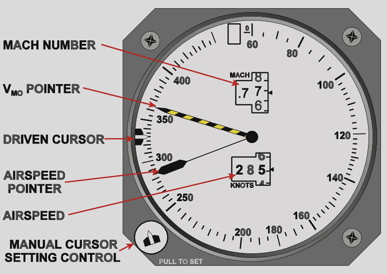
OVERSPEED WARNING ON ASI
Stall Warning System
The function of a stall warning system is to alert the pilot to the fact that the aircraft is approaching the stalling angle of attack in sufficient time for corrective action to be taken. The actual nature of the warning takes several different forms, depending upon the aircraft type and its behaviour at the point of the stall and thereafter. Since the stall occurs at a known angle of attack, the stall warning sensing device measures aircraft angle of attack and the stall warning system activates an alert before the stalling angle is reached.
Many aircraft provide some warning of the approach of a stall in the form of buffeting, followed by a pitch-down change of attitude as the centre of pressure moves rapidly aft on the wing. The buffeting is felt on the controls in aircraft with controls linked directly to the control surfaces, but with powered flying controls this is less likely to be the case and the natural stall warning may be so slight that the pilot might miss it in conditions of high work-load.
In aircraft with the horizontal stabiliser mounted at or near the top of the fin (so-called T-tail aircraft) a condition known as deep stall is likely to develop if prompt recovery action is not taken immediately a stall warning is received. In aircraft having this configuration the stall warning has to be more direct than a simple aural alert; initially the system applies vibration to the control column (stick shaking) and in some aircraft, if pilot response is not immediate, it is followed by a forward pressure to the column (stick pushing).
The stall warning system comprises of input from various systems, since the stall angle depends on the position of slaps, flaps. The inputs received to the stall warning module are:
-
Angle of attack sensor
-
Flap Position
-
Slat Position
-
Airspeed from ADC
-
Landing Gear position
-
Thrust

STALL WARNING SYSTEM
Angle of attack sensing
In general aviation aircraft the angle of attack sensing device often used consists of a vane mounted in the leading edge of a wing at the point where stagnation occurs at normal flight attitudes. Under these circumstances the vane occupies a neutral, mid-position with the air pressure approximately equal on both its upper and lower surface.
As the aircraft attitude becomes increasingly pitched nose-up, the stagnation point moves toward the lower surface of the wing and the pressure beneath the vane becomes significantly greater than that above it. The vane therefore moves upward and closes a switch attached to it, completing an electrical circuit to the stall warning horn in the cockpit. The mechanism is adjustable, so that it can be set to activate the stall warning at a precise angle of attack, slightly lower than the stalling angle.

LEADING EDGE TYPE ANGLE OF ATTACT SENSOR
Some light aircraft and training types use an even simpler stall warning device known as a plenum chamber. An adjustable plate with a slot cut in it is mounted on a wing leading edge and adjusted so that the slot aligns with the stagnation point at normal flight attitudes. The slot is connected to a chamber, which is in turn connected by tube to a reed-operated horn in the cockpit.
When the angle of attack reaches a preset value, the reduced pressure at the slot induces airflow through the horn, vibrating the reed to provide an aural alert to the pilot.

PLENUM CHAMBER TYPE ANGLE OF ATTACK SENSOR
In larger aircraft, where the stall warning may well be accompanied by stick shaking or pushing, a more sophisticated type of angle of attack sensor is typically used. This uses an aerodynamic vane that projects into the airstream at a location unaffected by disturbances, usually on the side of the fuselage toward the nose of the aircraft. The vane is dynamically balanced and is connected to the rotor of a synchro, which transmits an electrical signal proportional to the angle taken by the vane, relative to a preset null position.

ANGLE OF ATTACK SENSOR LOCATION
Since the vane has a symmetrical aerofoil section and is freely balanced, it naturally aligns itself with the airstream when the aircraft is in flight. Thus, as aircraft pitch attitude changes, the vane remains aligned with the airstream and the aircraft moves in pitch relative to the vane. The relative movement is sensed by the vane synchro and transmitted to the stall warning system and the angle of attack indicator, where fitted.
An angle of attack vane is illustrated in Figure. Upon installation, the vane unit is accurately aligned by locating pins on the fuselage that engage in holes in the vane unit mounting flange.
Because the stalling angle of attack changes when flaps and slats are deployed, it is necessary to bias the vane synchro with inputs from the flap and slat position synchros to adjust the stall warning angle of attack accordingly.

ANGLE OF ATTACK SENSOR
Stick shaker
In aircraft where an immediate response to a stall warning is required it is usual to install a stick shaker. This consists of a d.c. motor that, when activated, applies vibration to the control column, immediately drawing the pilot's attention to the need to apply forward stick to reduce the pitch attitude of the aircraft.
This method is chosen because it is reminiscent of the pilot's earliest flight training in stall recovery procedures in a training aircraft.
The motor will continue to vibrate the control column until the angle of attack sensor senses that the aircraft's angle of attack has reduced below the warning threshold, whereupon the system cuts off d.c. supply to the motor.
Switching the system control switch to TEST, with the aircraft on the ground, activates a small motor to rotate the dial of an indicator, proving that the control circuit is functional.

STALL WARNING SYSTEM
Stick pusher
Aircraft with poor stall recovery characteristics, such as T-tail configured aircraft, may be fitted with a system that actually pushes the control column forward if the pilot does not respond to the stick shaker. It was found with the BAC 1-11 and Trident aircraft, both high T-tailed with aft-mounted engines, that if stall recovery was not promptly executed, the aircraft was prone to enter a deep-stall (super stall) condition from which recovery is almost always impossible.
The reason for this is that the tailplane (horizontal stabiliser) becomes stalled by the turbulent airflow from the stalled wings and all longitudinal control is lost. The aircraft enters a steep descent in a nose-up, wings level attitude. Thus, it is essential that rapid corrective action is taken in aircraft of this configuration, hence the stick pusher. The motive force for pushing the control column is often of the linear actuator type and the signal to it is passed through the elevator channel feel and centring unit. Activation of the stick pusher automatically disengages the automatic flight control system.